Moving mechanism of mineral excavator

A motion mechanism and excavator technology, which is applied in the direction of mechanically driven excavators/dredgers, etc., to increase the load capacity, optimize the force condition, and improve the capacity of mining operations.

Pending Publication Date: 2019-08-23
ZHEJIANG UNIV OF TECH
View PDF0 Cites 0 Cited by
  • Summary
  • Abstract
  • Description
  • Claims
  • Application Information

AI Technical Summary

Problems solved by technology

At present, there are few designs that combine hydraulic cylinders and wire ropes to design the kinematic mechanism of mining front shovel excavators.

Method used


Image

  • Moving mechanism of mineral excavator

Examples


Embodiment Construction

[0017] The technical solution of the present invention will be further described below in conjunction with the accompanying drawings.

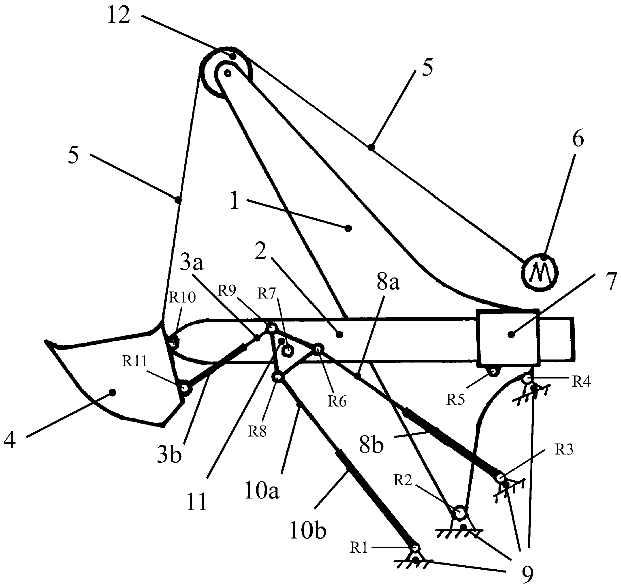
[0018] The motion mechanism of the mining excavator includes a fixed body 9, a boom 1, a stick 2, a bucket 4, bucket cylinders (3a, 3b), stick hydraulic cylinders (10a, 10b), auxiliary hydraulic cylinders (8a, 8b ), rotating connection plate 11, stick driving device 7, wire rope 5, wire rope guide wheel 12 and wire rope driving motor 6;

[0019] With the arm 2 as the boundary, the excavating motion mechanism of the present invention can be divided into upper and lower parts: the upper part is a wire rope excavating mechanism, which consists of a boom 1, an arm 2, a bucket 4, a wire rope 5, and a wire rope guide wheel 12 Composed of a wire rope drive motor 6; the lower part is a hydraulic cylinder excavation mechanism, which consists of a stick 2, a bucket 4, a bucket cylinder (3a, 3b), a stick hydraulic cylinder (10a, 10b), an auxiliary hydrau...


PUM


Abstract

A moving mechanism of a mineral excavator is characterized in that a steel wire rope driving motor is mounted on a fixing machine body, wherein a steel wire rope extends out from the steel wire rope driving motor and then moves round a steel wire rope pulley to be connected to a bucket; the fixing machine body is hinged with a movable arm, and the movable arm is hinged with a bucket rod driving device; the bucket rod driving device is capable of driving a bucket rod to telescope; the head end of the bucket rod is hinged with the bucket, and the front end of the bucket rod is hinged with a rotating connecting plate; the small end of a hydraulic oil cylinder of the bucket is hinged with the rotating connecting plate, and the big end of the hydraulic oil cylinder of the bucket is hinged withthe bucket; the small end of a hydraulic oil cylinder of the bucket rod is hinged with the rotating connecting plate, and the big end of the hydraulic oil cylinder of the bucket rod is hinged with thefixing machine body; the small end of a secondary hydraulic oil cylinder is hinged with the rotating connecting plate, and the big end of the secondary hydraulic oil cylinder is hinged with the fixing machine body. With the adoption of the moving mechanism of the mineral excavator, the excavating working functions of a common mineral excavator can be realized; the carrying capacity of the bucketand the bucket rod can be improved; the force bearing condition of the bucket rod is optimized; the mining working capacity is improved; the impact to the mining work is reduced; the working efficiency is improved; and the service life of the bucket rod is prolonged.

Description

technical field [0001] The invention relates to an excavating motion mechanism of a mine-used front shovel excavator. Background technique [0002] The mining front shovel excavator is an important construction machinery equipment for open-pit ore mining. The existing mining front shovel excavators mainly include hydraulic excavators and wire rope electric shovels. The hydraulic excavator mainly uses the hydraulic cylinder as the main power source to drive the boom, stick and bucket of the excavator to work, and the operation is flexible and has a wide range; the wire rope electric shovel mainly drives the excavator by the tension and release of the driving motor to the wire rope. The boom, stick and bucket work, but its digging force is the vertical component of the rope tension, so only part of the tension is utilized. At present, there are few designs that combine hydraulic cylinders and wire ropes to design the kinematic mechanism of mining front shovel excavators. In ...

Claims


Application Information

Patent Timeline
IPC IPC(8): E02F3/28E02F3/36E02F3/38E02F3/40E02F3/42E02F3/46E02F3/58
CPCE02F3/28E02F3/36E02F3/38E02F3/40E02F3/42E02F3/46E02F3/58
Inventor 宁晓斌王宇坤
Owner ZHEJIANG UNIV OF TECH
Why Eureka
Try Eureka