
Rotation speed regulating method for CD machine to prevent CD from producing vibration

An adjustment method and technology of optical disc drive, applied in the direction of vehicle speed control/adjustment/indication, etc., can solve the problems of large swing force, mechanical structure vibration of optical disc drive, increase of data reading time, etc., to reduce noise and data. Reading time, anti-vibration effect

Inactive Publication Date: 2003-02-12
BENQ CORP
View PDF6 Cites 0 Cited by
  • Summary
  • Abstract
  • Description
  • Claims
  • Application Information

AI Technical Summary

Problems solved by technology

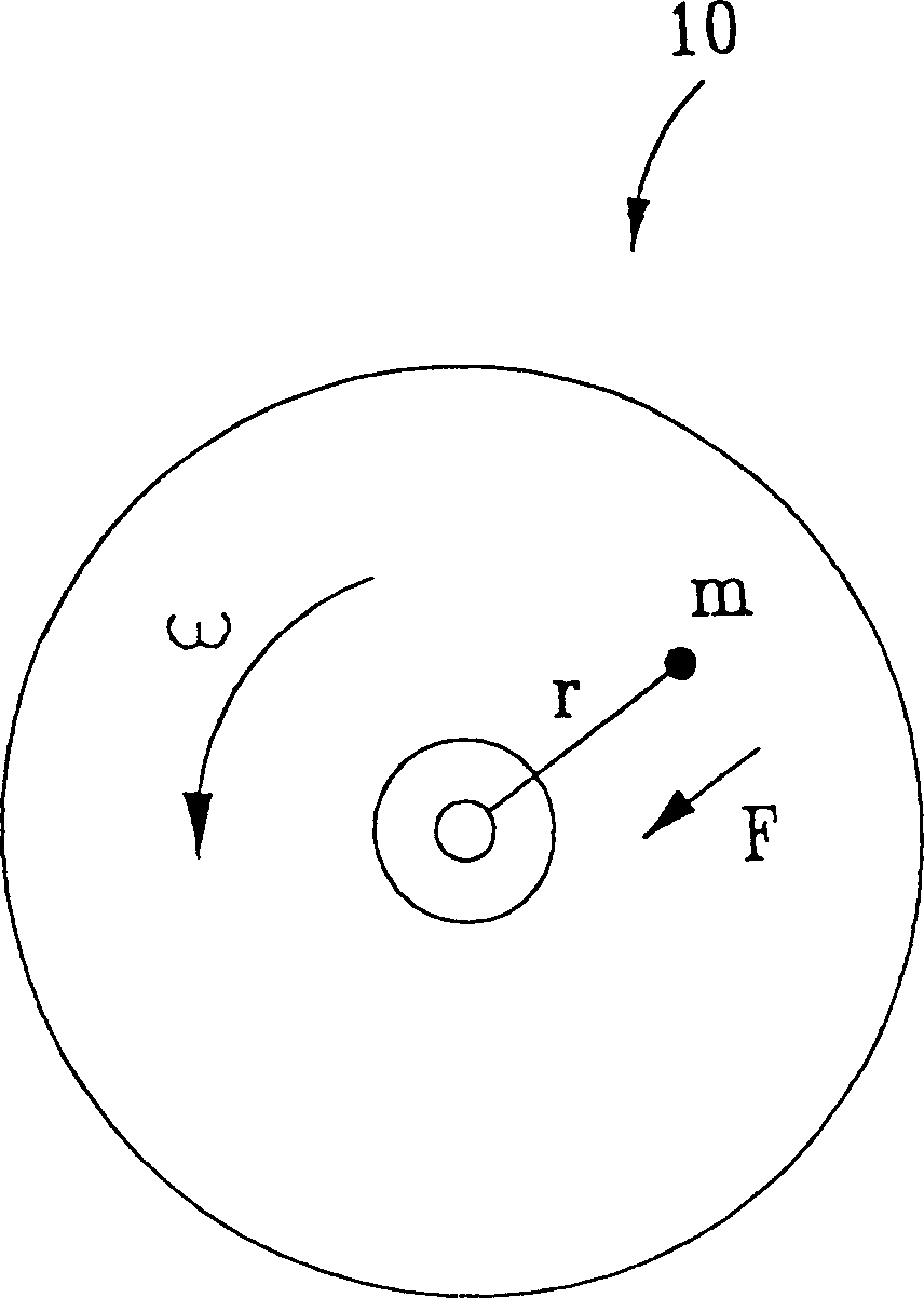
Therefore, even if the unbalance mr of the optical disc 10 is not large, when the optical disc 10 is rotated at a high speed, a large centrifugal force may be generated, and a large swinging force may be generated, thereby causing the mechanical structure of the optical disc drive to vibrate. Phenomenon
This vibration phenomenon not only produces noise, but also increases data reading time

Method used

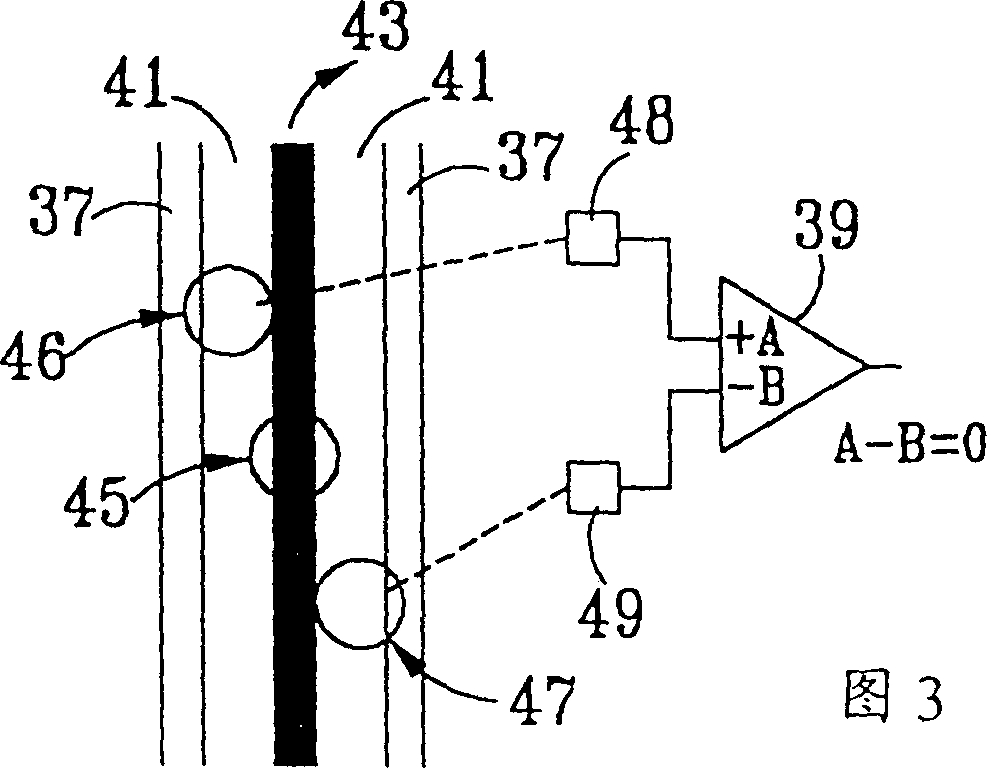

Image

  • Rotation speed regulating method for CD machine to prevent CD from producing vibration
  • Rotation speed regulating method for CD machine to prevent CD from producing vibration
  • Rotation speed regulating method for CD machine to prevent CD from producing vibration

Examples


Embodiment Construction

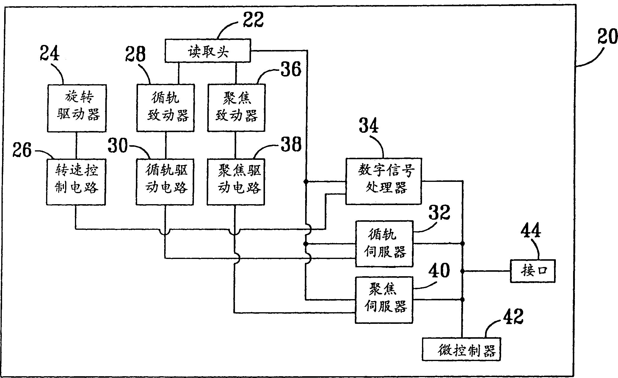
[0012] Please refer to figure 2 . figure 2 It is a functional block diagram of an optical disc drive 20 that can use the rotational speed adjustment method of the present invention. The optical disc drive 20 includes a pickup head 22 for reading data stored on a track of an optical disc and generating a data signal, a tracking servo signal and a focus servo signal. A rotary driver 24 is used to rotate the optical disk; a rotational speed control circuit 26 is used to control the rotational speed of the rotary driver 24; a track actuator 28 is used to move the pickup head 22 along the radial direction of the optical disk position; a tracking drive circuit 30, used to control the tracking actuator 28; a tracking servo 32, used to control the tracking according to the tracking servo signal generated by the read head 22 and a tracking loop gain The driving circuit 30 enables the tracking actuator 28 to radially move the pick-up head 22 to follow the track of the optical disc. ...


PUM


Abstract

The CD machine consists of reading head, rotation driver, rotation speed controller circuit, loop driver, loop driving circuit and loop servo. The rotation speed regulation includes the steps of reducing the loop gain to one preset value; increasing the rotation speed of the rotary driver gradually by using the rotation speed controller circuit, judging whether or not there is vibration by means of the vibration judging program and the loop servo signal, and recording the rotation speed when vibration takes place; setting the rotation speed of CD machine to one value lower than the rotation speed when vibration takes place; and restoring the gain of the loop.

Description

technical field [0001] The invention relates to a method for adjusting the rotational speed of an optical disc drive, in particular to a method for adjusting the rotational speed of an optical disc drive which can prevent optical discs from vibrating. Background technique [0002] Please refer to figure 1 . figure 1 It is a schematic diagram of an optical disc 10 with unbalanced quality. The center of mass of the optical disc 10 may deviate from the center of the disc circle due to size variation during manufacture, uneven material, or other factors. Assuming that the mass of the optical disc 10 is m, and the distance between the center of mass and the center of the disc is r, the optical disc 10 has an unbalance of mr (gram-millimeter). When the optical disc 10 rotates at an angular velocity ω, a centrifugal force F will be generated, and its equation is: [0003] F=mrω 2 [0004] The magnitude of the centrifugal force F is proportional to the unbal...

Claims


Application Information

Patent Timeline
Patent Type & Authority Patents(China)
IPC IPC(8): G11B15/46
Inventor 颜孟新古政杰王威
Owner BENQ CORP
Learn More