Air intake and exhaust pipe structure of automobile engine

An automobile engine, intake and exhaust technology, applied in the direction of engine components, machines/engines, exhaust devices, etc., can solve the problems that the seal cannot be completely sealed, the engine car fails, and the car engine is damaged.

Active Publication Date: 2019-08-23
安徽中威机械工业有限公司
View PDF9 Cites 1 Cited by
  • Summary
  • Abstract
  • Description
  • Claims
  • Application Information

AI Technical Summary

Problems solved by technology

[0003] It has been more than 100 years since the first automobile was invented, and automobiles have gradually entered the lives of the people; with the popularity of automobiles, many shortcomings of automobiles have become increasingly apparent; one of the many shortcomings is that once the automobile engine enters water, it will be seriously damaged. Especially in cities after heavy rain, there will be many car failures caused by engine water
[0004] Although there are already plans on the market to improve the wading ability of the car by setting two air intake ports, one high and one low, but the existing solutions all prevent water ingress by sealing the lower air intake port with a seal, but due to the The air pipe will vibrate with the vibration of the engine, and the seal used to seal the air intake pipe is very easy to loosen, and the loose seal is likely to fail to seal completely. At this time, the external water can easily pass through the poorly sealed seal. into the engine, causing engine damage

Method used


Image

  • Air intake and exhaust pipe structure of automobile engine
  • Air intake and exhaust pipe structure of automobile engine
  • Air intake and exhaust pipe structure of automobile engine

Examples


Embodiment Construction

[0030] In order to facilitate the understanding of those skilled in the art, the present invention will be further described in detail below with reference to the drawings and embodiments.

[0031] Please refer to Figure 1-3 , the embodiment of the present invention includes:

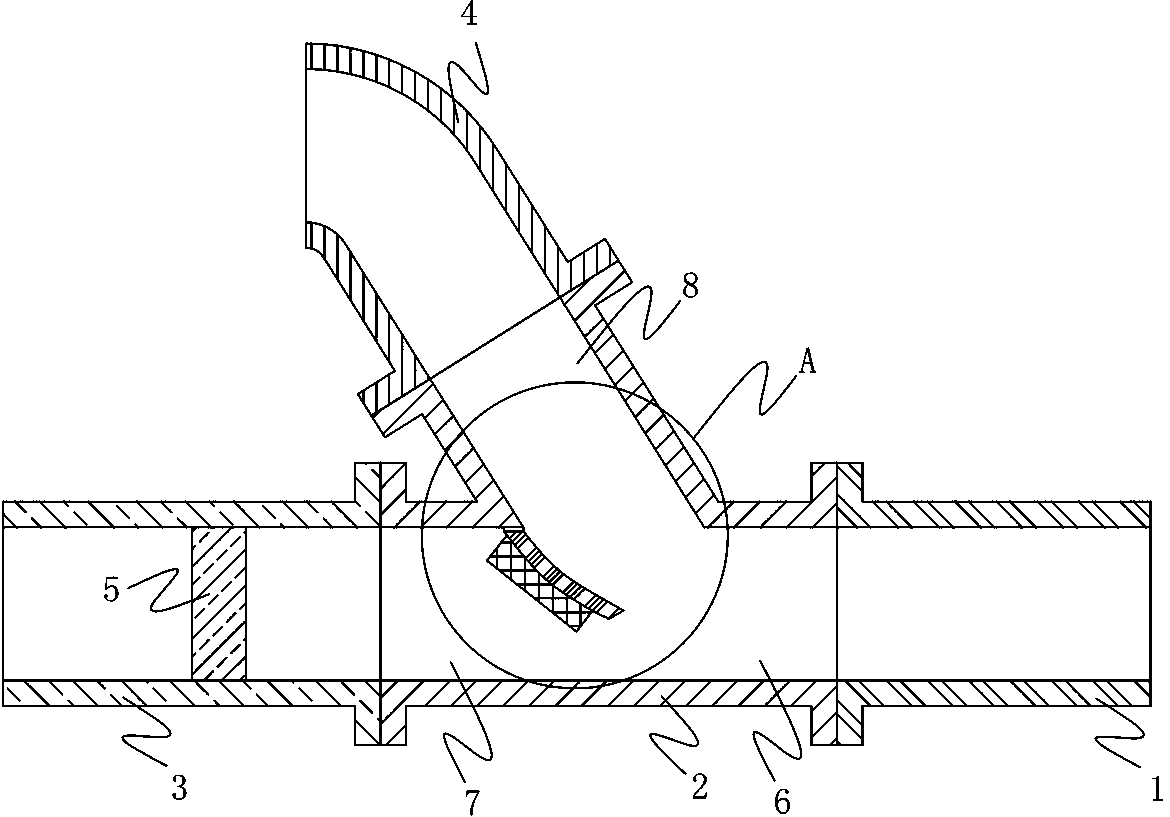
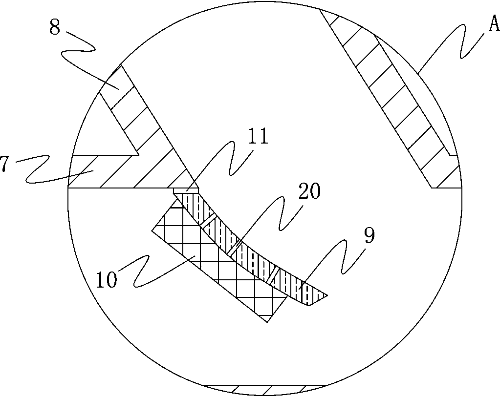
[0032] An intake and exhaust duct structure of an automobile engine, comprising an intake duct connected with an air filter and an exhaust duct connected with a muffler; the intake duct includes an intake main pipe 1 connected with the air filter, an intake main pipe 1 connected to the three-port joint 2, the intake branch pipe 1 connected to the three-port joint 2, the intake branch pipe 2 connected to the three-port joint 2 4, the opening of the intake branch pipe 2 4 is higher than the opening of the intake branch pipe 1 3 Height, the fan 5 is arranged in the pipe of the air intake branch pipe 1, and the three-port joint 2 includes the first connecting channel 6, the second connecting channel 7, an...


PUM


Abstract

The invention discloses an air intake and exhaust pipe structure of an automobile engine; the air intake and exhaust pipe structure of the automobile engine comprises an air intake pipe connected withan air filter and an air exhaust pipe connected with a silencer; the air intake pipe comprises an air intake main pipe connected with the air filter, a three-port joint connected with the air intakemain pipe, an air intake branch pipe I connected with the three-port joint and an air intake branch pipe II connected with the three-port joint; the height of the opening of the air intake branch pipeII is higher than that of the opening of the air intake branch pipe I; a fan is arranged in the pipe of the air intake branch pipe I; the three-port joint comprises a first joining channel, a secondjoining channel and a third joining channel which are connected mutually; the first joining channel is connected with the air intake main pipe, the second joining channel is connected with the air intake branch pipe I, the third joining channel is connected with the air intake branch pipe II, and the junction of the second joining channel and the third joining channel is provided with a curved surface blocking piece. The air intake and exhaust pipe structure provided by the invention is capable of avoiding entering water in the engine effectively.

Description

technical field [0001] The invention relates to the field of automobiles, in particular to an intake and exhaust pipe structure of an automobile engine. Background technique [0002] A car is a non-track-bearing vehicle driven by power and having 4 or more wheels. [0003] It has been more than 100 years since the first automobile was invented, and automobiles have gradually entered the lives of the people; with the popularity of automobiles, many shortcomings of automobiles have become increasingly apparent; one of the many shortcomings is that once the automobile engine enters water, it will be seriously damaged. Especially in cities after heavy rain, there will be many car failures caused by engine water. [0004] Although there are already plans on the market to improve the wading ability of the car by setting two air intake ports, one high and one low, but the existing solutions all prevent water ingress by sealing the lower air intake port with a seal, but due to the ...

Claims


Application Information

Patent Timeline
Patent Type & Authority Applications(China)
IPC IPC(8): F02M35/10F02M35/104F02M35/16F01N13/08F01N13/10
CPCF01N13/08F01N13/10F01N2470/00F02M35/10091F02M35/10262F02M35/104F02M35/16
Inventor 徐伟明
Owner 安徽中威机械工业有限公司
Why Eureka
Try Eureka