Low-noise efficient energy-saving centrifugal fan
A high-efficiency, energy-saving, centrifugal fan technology, applied in electromechanical devices, mechanical equipment, control of mechanical energy and other directions, can solve problems such as loss of energy, increase in energy consumption, increase in blade resistance, etc., to reduce reactive power loss and energy loss, reduce noise and Energy damage, reducing the effect of external noise
- Summary
- Abstract
- Description
- Claims
- Application Information
AI Technical Summary
Problems solved by technology
Method used
Image
Examples
Embodiment 1
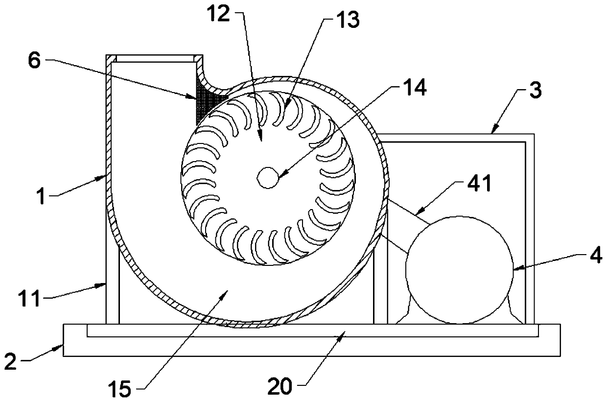
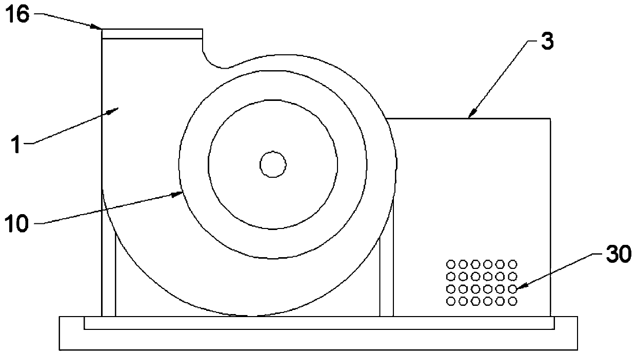
[0024] see Figure 1~6 , in an embodiment of the present invention, a low-noise, high-efficiency, energy-saving centrifugal fan includes a fan volute 1, the front panel of the fan volute 1 is provided with a flared air collection port 10, and the inside of the flared air collection port 10 is installed with the following The center of the flaring air collection port 10 is the impeller disc 12 whose center of rotation is the center of rotation. A diffuser air duct 15 for diffuser and exhaust is arranged around the impeller disc 12. A plurality of surrounding air ducts are vertically fixed on the front panel of the impeller disc 12. A plurality of downwind blades 13 arranged at the flaring air collection port 10, the bending direction of the downwind blades 13 is consistent with the natural movement track of the gas, the impeller disk 12 is fixedly connected with the output shaft of the driving device through the impeller shaft 14, and the driving device The whole is built in th...
Embodiment 2
[0032] The difference between this embodiment and embodiment 1 is:
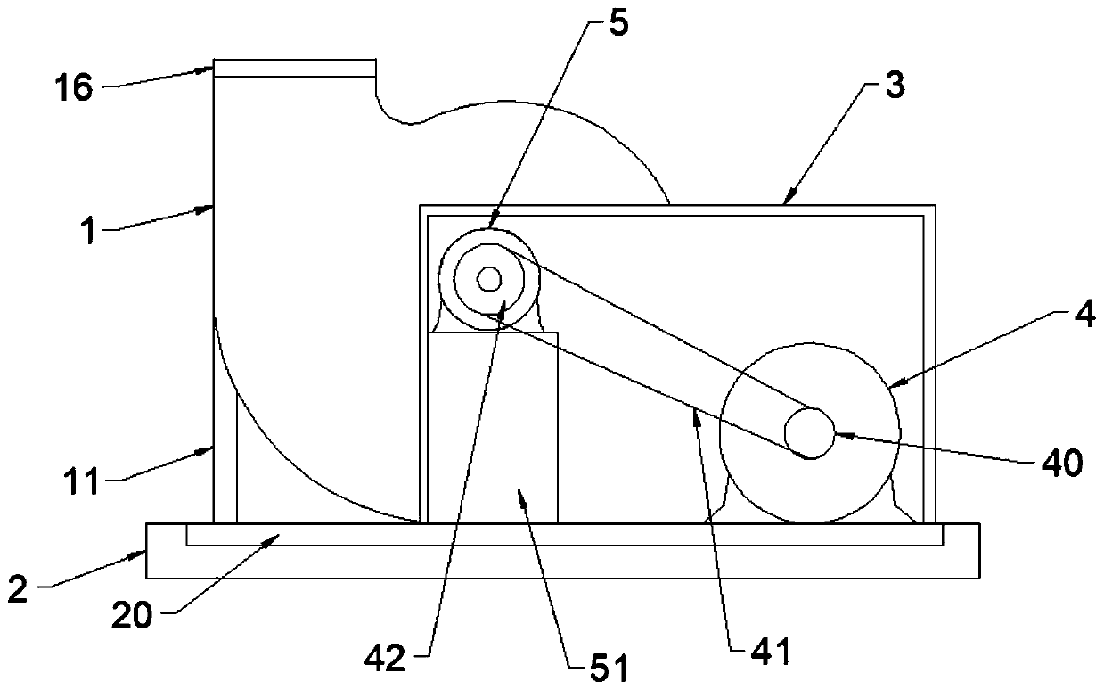
[0033] The soundproof cabinet 3 is provided with a bearing seat 5 for enhancing the stability of the impeller shaft 14. The bearing seat 5 is composed of a sealed groove box, and the bearing seat 5 is fixed on the top surface of the soundproof cabinet 3 through a bearing frame 51 as a whole. The front and rear panels of the bearing housing 5 are rotatably fixed with two bearings, and a supporting main shaft 50 is rotated between the bearings. The front end of the supporting main shaft 50 is fixedly connected with the impeller shaft 14, and the rear end of the supporting main shaft 50 is It is fixedly connected with the shaft pulley 42.
[0034] The top opening of the diffuser duct 15 is fixed with a ring of sealing cushions 16 .
[0035] The working principle of the present invention: the set bearing seat 5 mainly reduces the longitudinal compression force of the impeller shaft 14 at the place where the rear...
PUM
 Abstract
Description
Claims
Application Information
 - R&D
- Intellectual Property
- Life Sciences
- Materials
- Tech Scout
- Unparalleled Data Quality
- Higher Quality Content
- 60% Fewer Hallucinations
Browse by: Latest US Patents, China's latest patents, Technical Efficacy Thesaurus, Application Domain, Technology Topic, Popular Technical Reports.
© 2025 PatSnap. All rights reserved.Legal|Privacy policy|Modern Slavery Act Transparency Statement|Sitemap|About US| Contact US: help@patsnap.com


