
Hydraulic closed type flushing loop

A closed-loop technology, used in fluid pressure actuation devices, fluid pressure actuation system components, mechanical equipment, etc., can solve the problems of lack of oil in the motor casing, excessive flushing flow, and easy damage to the motor, and avoid The effect of dry grinding

Pending Publication Date: 2019-08-23
无锡市钻通工程机械有限公司
View PDF0 Cites 3 Cited by
  • Summary
  • Abstract
  • Description
  • Claims
  • Application Information

AI Technical Summary

Problems solved by technology

[0003] When the hydraulic motor is at a high position, due to the siphon phenomenon, the motor casing may lack oil. When rotating at high speed, it will cause dry grinding due to lack of oil, which will easily damage the motor; when the machine is just started for construction in extremely cold regions, the oil in the closed circuit cannot be circulated and heated. ;When the closed circuit high-pressure oil ports A and B are switched quickly, due to the lag of the hot oil shuttle valve, the flushing flow will be too large

Method used


Image

  • Hydraulic closed type flushing loop
  • Hydraulic closed type flushing loop
  • Hydraulic closed type flushing loop

Examples


Embodiment Construction

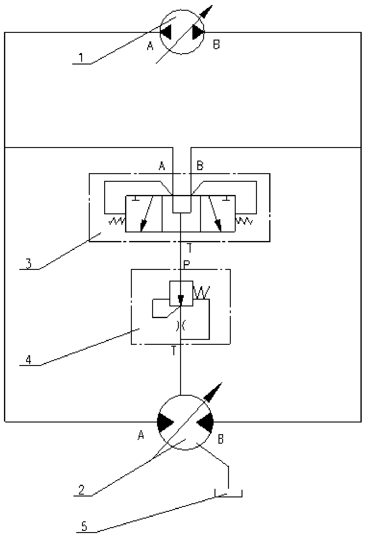
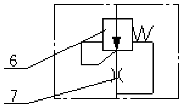
[0013] Such as figure 1 As shown: a reliable hydraulic closed flushing circuit includes a hydraulic oil pump 1, a hydraulic motor 2, a hot oil shuttle valve 3, a speed control valve 4 and a hydraulic oil tank 5; port and the first oil inlet A of the hot oil shuttle valve 3 are connected through the pipeline, and the B port of the hydraulic oil pump 1 is connected with the B port of the hydraulic motor 2 and the second oil inlet B of the hot oil shuttle valve 3 through the pipeline The oil outlet T of the hot oil shuttle valve 3 is connected with the oil inlet P of the speed regulating valve 4 through the pipeline, and the oil outlet T of the speed regulating valve 4 is connected with the first oil discharge port of the hydraulic motor 2 through the pipe. The second oil drain port of the hydraulic motor 2 is connected with the hydraulic oil tank 5 through the pipeline.

[0014] Further, the first oil inlet A of the hot oil shuttle valve 3 communicates with the left spring cha...


PUM


Abstract

The invention relates to a hydraulic closed type flushing loop and belongs to the technical field of hydraulic equipment. The hydraulic closed type flushing loop comprises a hydraulic oil pump, a hydraulic motor, a hot oil shuttle valve and a speed adjustment valve. An opening A of the hydraulic oil pump communicates with an opening A of the hydraulic motor and a first oil inlet A of the hot oil shuttle valve. An opening B of the hydraulic oil pump communicates with an opening B of the hydraulic motor and a second oil inlet B of the hot oil shuttle valve. An oil outlet T of the hot oil shuttlevalve communicates with an oil inlet P of the speed adjustment valve. An oil outlet T of the speed adjustment valve communicates with a first oil drainage opening of the hydraulic motor. A second oildrainage opening of the hydraulic motor communicates with a hydraulic oil tank. After a closed type system is started, the nominal flushing flow can be generated no matter whether people operate thesystem or not; when the hydraulic motor is at the high position, part of hydraulic oil enters a shell of the hydraulic motor after start, and dry rubbing is avoided; the defect that heating cannot beconducted after start can be avoided; the flushing flow is forced to be constant through the speed adjustment valve; and the problem that the flushing flow is excessively large when a high-pressure oil opening A and a high-pressure oil opening B are switched rapidly can be avoided.

Description

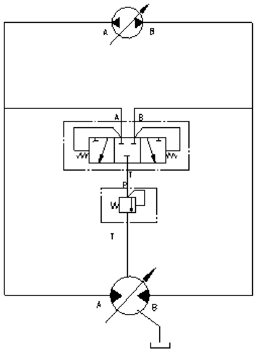
technical field [0001] The invention relates to a hydraulic closed flushing circuit, which belongs to the technical field of hydraulic equipment. Background technique [0002] The current hydraulic closed flushing circuit such as image 3 As shown, the middle position of the hot oil shuttle valve is that the high pressure oil port A, the high pressure oil port B and the oil outlet T port are all unconnected, and the hot oil shuttle valve is directly connected in series with the hydraulic oil tank with a relief valve. [0003] When the hydraulic motor is at a high position, due to the siphon phenomenon, the motor casing may lack oil. When rotating at high speed, it will cause dry grinding due to lack of oil, which will easily damage the motor; when the machine is just started for construction in extremely cold regions, the oil in the closed circuit cannot be circulated and heated. ;When the closed circuit high-pressure oil ports A and B are switched quickly, due to the hyster...

Claims


Application Information

Patent Timeline
Patent Type & Authority Applications(China)
IPC IPC(8): F15B21/00F15B21/0423
CPCF15B21/00F15B21/042
Inventor 徐彬彬董志伟于峰贾绍宽
Owner 无锡市钻通工程机械有限公司
Learn More