Sensing combination gap sheet and machining method thereof

A technology that combines gaps and processing methods, applied in the field of gaps, can solve problems such as deterioration of output accuracy of parts, loss of their own accuracy, and attenuation of output accuracy, so as to improve the normal service life and accuracy stability, and reduce the risk of not being identified , Guarantee the effect of matching precision

Pending Publication Date: 2019-08-23
苏州济和精密传动系统有限公司
View PDF0 Cites 0 Cited by
  • Summary
  • Abstract
  • Description
  • Claims
  • Application Information

AI Technical Summary

Problems solved by technology

However, once these high-precision transmission equipment is in an environment with harsh operating conditions for a long time, there will be slight looseness between the matching parts, and this looseness is difficult to be quickly identified, which will eventually lead to rapid output accuracy. Attenuation leads to instability; at the same time, the gap piece assembled between the matching parts will further lose its own precision as the parts are loosened and worn, making the output accuracy of the parts worse and lower
The current detection method can only adopt manual timely detection and spot inspection, which is time-consuming and laborious, and also greatly reduces the efficiency and normal life of the equipment

Method used


Image

  • Sensing combination gap sheet and machining method thereof
  • Sensing combination gap sheet and machining method thereof
  • Sensing combination gap sheet and machining method thereof

Examples


Embodiment 1

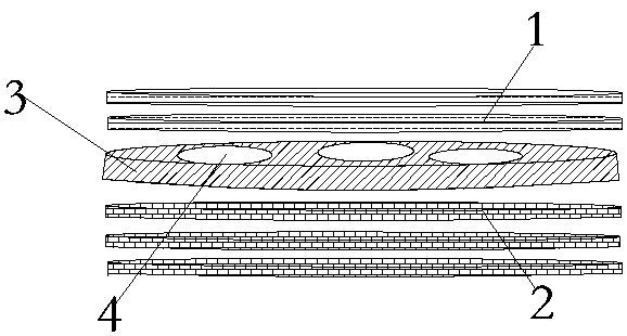
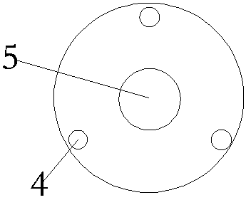
[0051] Such as figure 2 The combined spacer in this embodiment shown is circular with a through hole 5 in the middle. The diameter of the composite spacer is 130±0.3mm, the total thickness is 3.2±0.01mm, and the thickness of the mosaic layer 3 is 2.5±0.1mm. Such as figure 1 As shown, the composite gap sheet includes a front layer 1, a back layer 2, an inlay layer 3 and a pressure sensor. The mosaic layer 3 is located between the front layer 1 and the back layer 2, and the mosaic layer is provided with three installation holes 4, and the installation holes 4 are arranged on the mosaic layer at equal intervals. One, the thickness of the pressure sensor is slightly thicker than the depth of the mounting hole 4, the pressure sensor is installed in the mounting hole 4, the exposed part of the pressure sensor is located in the reserved hole, the front layer 1 includes at least two first adhesive layers, and the back layer 2 It includes at least two second adhesive layers, each o...

Embodiment 2

[0065] The difference from Example 1 is that in the step of gluing and sticking, the front layer is pasted with 3 pieces of the first sticking layer of 0.1mm, 0.1mm*3=0.3mm, and the back layer of this embodiment adopts the first sticking layer of three kinds of thickness. Two paste layers, namely 0.1mm, 0.05mm and 0.02mm, that is, the thickness of the back layer is 0.1*3+0.05*1+0.02*3=0.4mm. .

Embodiment 3

[0067] The difference from Embodiment 1 is that the combined gap sheet in this embodiment is rectangular, and the three installation holes are equally spaced on the mosaic layer. The piezoresistive pressure sensor is arranged in the installation hole, and the length of the combined gap sheet is 10±0.3 mm, the width is 7±0.3mm.


PUM

PropertyMeasurementUnit
thicknessaaaaaaaaaa
thicknessaaaaaaaaaa
sizeaaaaaaaaaa

Abstract

The invention relates to a sensing combination gap sheet. The sensing combination gap sheet comprises a front surface layer, a back surface layer, an embedding layer and pressure sensors, wherein theembedding layer is positioned between the front surface layer and the back surface layer, at least one mounting hole is formed in the embedding layer, the pressure sensors are arranged in the mountingholes, the front layer comprises at least two layers of strippable first stickup layers, and the back layer comprises at least two layers of strippable second stickup layers. According to the sensingcombination gap sheet, no matter what kinds of working conditions assembly equipment parts operate under, limitation and influence are both avoided, a sensing function is achieved, the loose state between the matched parts can be rapidly recognized to the maximum degree, and the matching precision between the parts can be guaranteed.

Description

technical field [0001] The invention relates to the field of gap sheets, in particular to a sensing combination gap sheet and a processing method thereof. Background technique [0002] Due to the rapid development of the industrialization process in modern society, the requirements for product production are becoming more and more precise, so the precision gap sheet plays an indispensable role, because the precision gap sheet is made of high-precision, high-hardness, high-toughness precision steel belt Made by heat treatment and fine grinding. [0003] With the rapid development of domestic precision machining and automation fields, some manufacturers of high-precision equipment with high matching precision in the market will choose precision gap adjusting gaskets for matching and adjustment during the research and development process. Under normal circumstances, the spacer products will only have the most basic performance - no deformation on the surface, no burrs, and uni...

Claims


Application Information

Patent Timeline
Patent Type & Authority Applications(China)
IPC IPC(8): F16B43/00G01B5/06G01B5/18G01L1/20G01N3/08
CPCF16B43/00G01B5/06G01B5/18G01L1/20G01N3/08
Inventor 郝景章霍佳玉
Owner 苏州济和精密传动系统有限公司
Why Eureka
Try Eureka