
Low-frequency oscillator and multi-frequency array antenna

A low-frequency vibrator and array antenna technology, applied in antennas, antenna coupling, antenna arrays, etc., can solve problems affecting antenna radiation performance indicators, horizontal lobe width divergence, horizontal plane deformation, etc., to achieve flexible layout, simple feeding mode, Reduce the effect of occlusion

Inactive Publication Date: 2019-08-23
ZHONGTIAN BROADBAND TECH +1
View PDF8 Cites 5 Cited by
  • Summary
  • Abstract
  • Description
  • Claims
  • Application Information

AI Technical Summary

Problems solved by technology

At present, radiation units (high-frequency radiation units and low-frequency radiation units) working in different frequency bands are generally used to form arrays to realize multi-frequency base station antennas. However, since the high-frequency radiation units and low-frequency radiation units are placed in one antenna, the high-frequency The low-frequency radiation characteristics affect each other. When the distance between the two is small, the low-frequency radiation unit forms a large shield for the high-frequency radiation unit, which seriously affects the radiation performance index of the antenna, for example, causing part of the horizontal plane of the high-frequency radiation unit to deform. , the horizontal lobe width diverges, and the front-to-back ratio and cross-polarization ratio become worse
[0003] In order to overcome the problem of occlusion, the low-frequency oscillators in the prior art often use two sets of dipoles placed at ±45° to form a dual-polarized radiation unit to achieve a ±45° polarized far-field radiation pattern, resulting in a multi-frequency array In the antenna, the orthographic projections of the high and low frequency radiating elements coincide with each other
In addition, in the prior art, a ±45° polarized far-field radiation pattern is generated by connecting the horizontal oscillator and the vertical oscillator to the feed network of the power divider through the low-frequency radiation unit, and the feed is relatively complicated.

Method used


Image

  • Low-frequency oscillator and multi-frequency array antenna
  • Low-frequency oscillator and multi-frequency array antenna
  • Low-frequency oscillator and multi-frequency array antenna

Examples


Embodiment Construction

[0028] The following will clearly and completely describe the technical solutions in the embodiments of the present invention in conjunction with the accompanying drawings in the embodiments of the present invention. Obviously, the described embodiments are only some of the embodiments of the present invention, not all of them. Based on the embodiments of the present invention, all other embodiments obtained by persons of ordinary skill in the art without making creative efforts belong to the protection scope of the present invention.

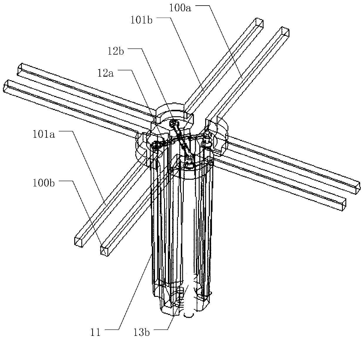
[0029] The core of the present invention is to provide a low-frequency dipole and a multi-frequency array antenna, which is used to overcome the problem of overlapping orthographic projections of the low-frequency radiating unit and the high-frequency radiating unit, and to feed the dipole arm by connecting the coaxial cable with the feeder , the feeding method is simple.

[0030] In order to enable those skilled in the art to better understand...


PUM


Abstract

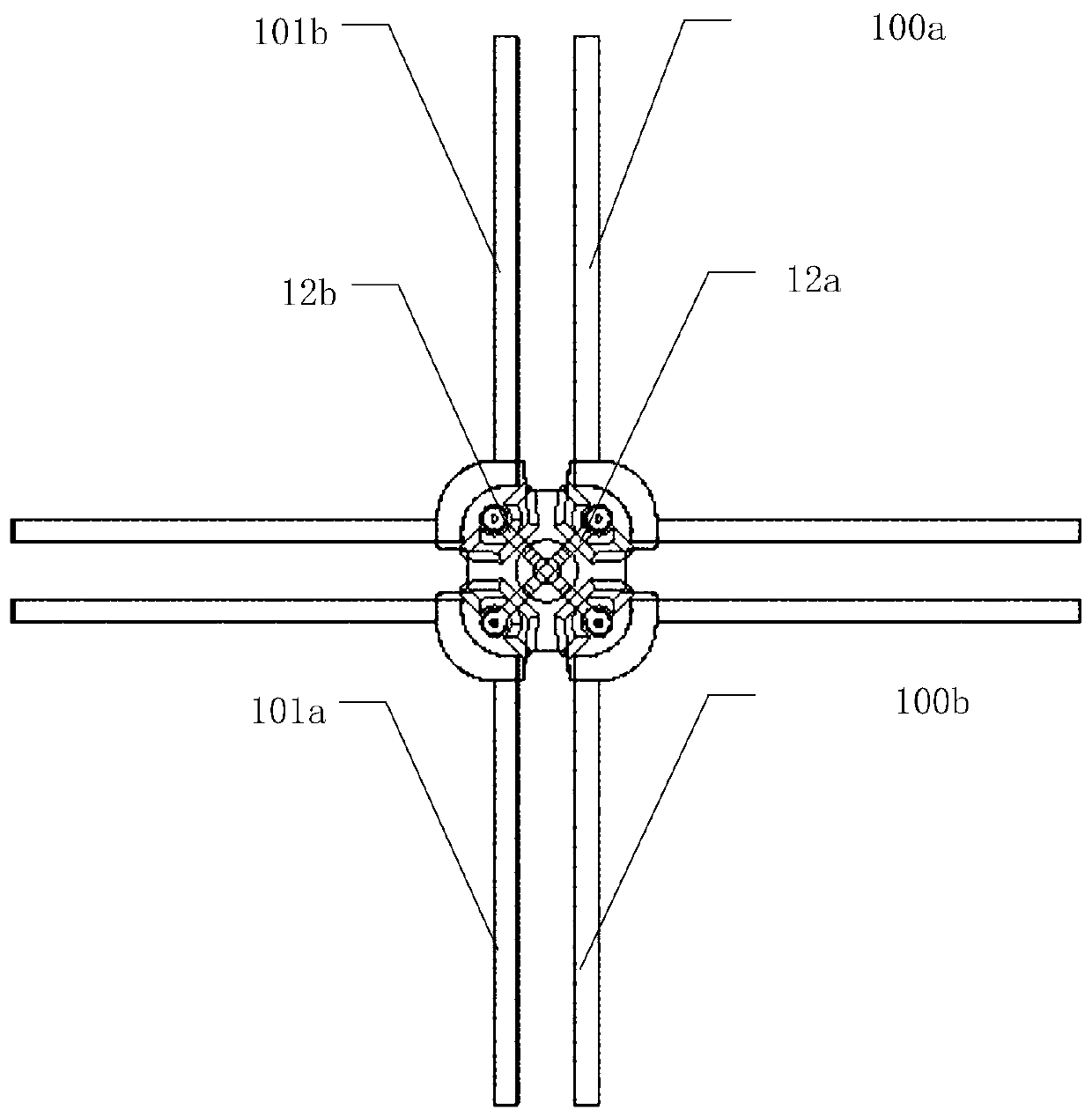
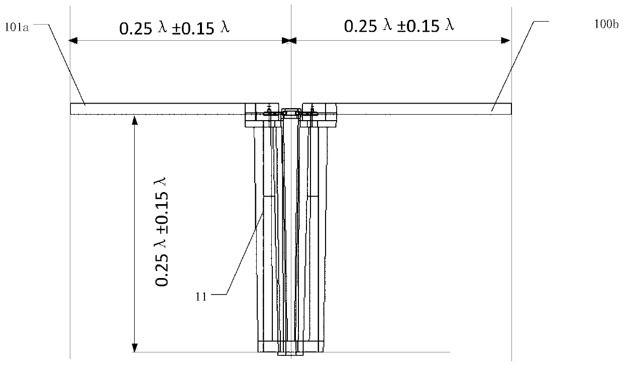
The invention discloses a low-frequency oscillator and a multi-frequency antenna. The low-frequency oscillator comprises an oscillator arm, a balun and feed sheets, wherein the oscillator arm comprises two pairs of L-shaped metal bars, the two pairs of L-shaped metal bars are respectively arranged in a diagonal manner and are horizontally arranged in a cross manner, and the two pairs of L-shaped metal bars are connected with the two feed sheets in a one-to-one correspondence manner. The feed sheets are connected with a coaxial cable to feed the oscillator arm. As the cross section area of theL-shaped metal bars is small, the shielding of a high-frequency radiation unit can be effectively reduced, and the electrical interference between a high frequency band and a low frequency band is reduced to the maximum extent. Moreover, the cross-shaped arrangement mode is favorable for the embedment in the high-frequency radiation unit in the multi-frequency antenna, so that the structure is compact and the arrangement is flexible under the condition that the size of a reflection plate is not increased. Finally, the feeding sheets and the coaxial cable are connected to feed the oscillator arm, and a power divider is not needed, so the feeding mode is simple. In addition, the common multi-frequency antenna comprises the low-frequency oscillator, which has the effect as the above.

Description

technical field [0001] The invention relates to the technical field of mobile communication, in particular to a low-frequency vibrator and a multi-frequency array antenna. Background technique [0002] With the development of mobile communication technology, people have higher and higher requirements on the communication rate, so the deployment and application of wireless communication systems in different frequency bands are increasing, resulting in more and more limited space on communication towers. In order to effectively reduce the installation space of the antenna on the iron tower, it is necessary to develop a multi-frequency antenna. At present, radiation units (high-frequency radiation units and low-frequency radiation units) working in different frequency bands are generally used to form arrays to realize multi-frequency base station antennas. However, since the high-frequency radiation units and low-frequency radiation units are placed in one antenna, the high-fre...

Claims


Application Information

Patent Timeline
Patent Type & Authority Applications(China)
IPC IPC(8): H01Q1/36H01Q1/50H01Q1/52H01Q21/00H01Q21/30H01Q1/12
CPCH01Q1/12H01Q1/36H01Q1/50H01Q1/523H01Q21/0006H01Q21/30
Inventor 顾晓凤王学仁张闪光颜玉洁丁建军郑朝义
Owner ZHONGTIAN BROADBAND TECH
Learn More