Supercharge Your Innovation With Domain-Expert AI Agents!

Cell Encapsulation Devices Containing Structural Spacers

A technology of cell encapsulation and spacer, which is applied in the direction of cell encapsulation, drug devices, microorganisms, etc., and can solve the problems of discontinuity, interruption, and reduction of internal volume on the external blood vessel formation surface

Active Publication Date: 2022-01-11
WL GORE & ASSOC INC +1
View PDF11 Cites 0 Cited by
  • Summary
  • Abstract
  • Description
  • Claims
  • Application Information

AI Technical Summary

Problems solved by technology

Internal welds are used to divide the lumen for better distribution of cells in the lumen, but this is done by compressing the device in one or more locations, which reduces the inner volume of the lumen
This reduction in internal volume may result in discontinuities and interruptions in the external vascularized surface

Method used


Image

  • Cell Encapsulation Devices Containing Structural Spacers
  • Cell Encapsulation Devices Containing Structural Spacers
  • Cell Encapsulation Devices Containing Structural Spacers

Examples


Embodiment 1

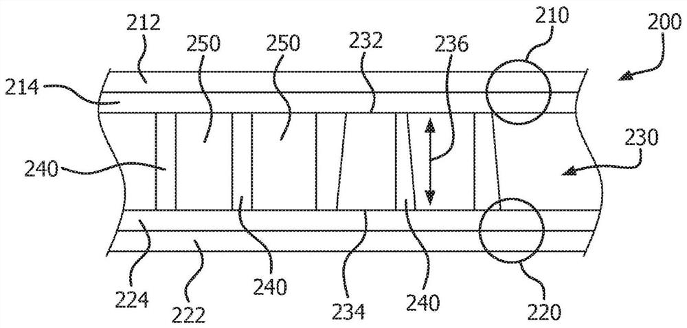
[0111] Obtain an ePTFE membrane with two cell-retaining (tight) layers separated by a vessel-forming (open) layer, as Figure 11 shown. A porous structural spacer formed of ePTFE connects the outer retention layer and forms a storage space for accommodating the battery therein. Two sheets of fluorinated ethylene propylene (FEP) film, each 4 mils thick (about 100 microns), were cut to form the perimeter seal of the cell encapsulation device. The cut FEP sheets were then stacked and aligned on the outer cell holding surface of a 1" x 2" (approximately 2.5 cm x 5 cm) sample of ePTFE membrane. A small area around the perimeter of the strip was protected with Kapton tape on both sides so that the perimeter could be left unbonded to allow access to the interior chamber.

[0112] The ePTFE / FEP stack was then compressed through a silicone die at a pressure of 90 psi (approximately 6.2 bar or 620.5 kPa) and heated with a pulsed heating tape at a temperature of 375°C for 30 seconds to...

Embodiment 2

[0114] In this example, thermoplastic polymers are used to create three-dimensional structural supports with patterned geometries. The cell-retaining ePTFE membrane is constrained in the ring. A patterned grid was placed on the surface of the ePTFE membrane to create a mask. The open areas of the grid translate into covered areas created by thermoplastic structural supports. Fluorinated ethylene propylene (FEP) powder was uniformly applied to the mask-covered confinement film by using a metal screen. Metal sieves with 150 micron and 710 micron openings were used. The FEP coating powder was melted and cured by placing the coated ePTFE membrane in an oven at 300°C for 10 minutes. Then remove the mask. The three-dimensional structural support remains on the surface of the cell retention membrane.

Embodiment 3

[0116] Samples A, B, C, and D were cut, each approximately 1" x 2" (approximately 2.5 cm x 5 cm), from a three-layer ePTFE composite comprising an inner layer with structural spacers and as shown in Table 1 as defined by the two outer layers. The inner layer is located between the two outer layers (ie, one on each side of the inner layer). Membrane properties are listed in Table 1.

[0117] Table 1

[0118]

[0119] Die sections of 4 mil (about 100 micrometers) thick fluorinated ethylene propylene (FEP) films were placed in parallel and adjacent to the outer layers of the film samples to form stacks. Each stack was then aligned with the device geometry listed on the silicone template and pulse thermally bonded. The perimeter seal was formed by compressing the material stack along the desired sealing geometry at 90 psi (about 6.2 bar or 620.5 kPa) and heating at 375°C for 30 seconds.


PUM

PropertyMeasurementUnit
lengthaaaaaaaaaa
sizeaaaaaaaaaa
sizeaaaaaaaaaa

Abstract

An implantable containment device for receiving and retaining a plurality of cells for insertion into a patient, eg, into a tissue bed, is disclosed. The device includes a chamber with a structural divider therein to maintain an average distance between a first inner surface and a second inner surface in the chamber and define at least one storage space for placing cells in the chamber.

Description

technical field [0001] The present invention relates to the field of medical devices, and in particular to a device comprising a structural spacer for encapsulating cells and implanting the cells in a patient. Background technique [0002] Biological therapies are an increasingly viable approach to treating peripheral artery disease, aneurysms, heart disease, Alzheimer's and Parkinson's diseases, autism, blindness, diabetes and other conditions. [0003] With regard to biological therapy in general, cells, viruses, viral vectors, bacteria, proteins, antibodies, and other biologically active moieties can be introduced into a patient by surgical or interventional methods that place the biologically active moiety in the patient's tissue bed. Typically, the biologically active moiety is placed in the device first, and the device is then inserted into the patient. Alternatively, the device can be inserted into the patient first, and the biologically active moiety added later. ...

Claims


Application Information

Patent Timeline
Patent Type & Authority Patents(China)
IPC IPC(8): A61L27/16A61L27/36A61F2/02A61M5/00A61M31/00A61M37/00C12N5/00
CPCA61L31/16A61L31/148A61L31/146A61L31/14A61L31/048A61L27/16A61L27/36A61L27/58A61L27/50A61L27/54A61L27/56A61K35/12A61K9/0024A61F2/022C12N5/0012A61L2400/16A61F2210/0076C08L27/18A61F2002/0081A61F2002/009A61F2210/0004A61F2210/0014A61F2210/0071A61F2240/001A61F2250/0068A61F2250/0023A61M5/00A61M31/002A61M37/00A61M37/0069A61M2202/097
Inventor E·H·库里L·赞姆博迪B·帕森斯P·D·德拉姆赫勒
Owner WL GORE & ASSOC INC
Features
  • R&D
  • Intellectual Property
  • Life Sciences
  • Materials
  • Tech Scout
  • Unparalleled Data Quality
  • Higher Quality Content
  • 60% Fewer Hallucinations
Learn More