Electric spindle structure of high-speed finish engraving machine

A technology of engraving machines and electric spindles, applied to metal processing machinery parts, large fixed members, metal processing equipment, etc., to achieve the effect of improving the overall tool release force and flexibility

Pending Publication Date: 2019-08-27
深圳市爱贝科精密工业股份有限公司
View PDF0 Cites 1 Cited by
  • Summary
  • Abstract
  • Description
  • Claims
  • Application Information

AI Technical Summary

Problems solved by technology

[0004] Aiming at the shortcomings in the use of the existing electric spindle proposed in the background technology, the present invention provides an electric spindle structure of a high-speed engraving machine, which has the advantages of higher tool release force and improved service life of components, and solves the problem of Problems raised in the background art above

Method used


Image

  • Electric spindle structure of high-speed finish engraving machine
  • Electric spindle structure of high-speed finish engraving machine
  • Electric spindle structure of high-speed finish engraving machine

Examples


Embodiment Construction

[0044]The following will clearly and completely describe the technical solutions in the embodiments of the present invention with reference to the accompanying drawings in the embodiments of the present invention. Obviously, the described embodiments are only some, not all, embodiments of the present invention. Based on the embodiments of the present invention, all other embodiments obtained by persons of ordinary skill in the art without making creative efforts belong to the protection scope of the present invention.

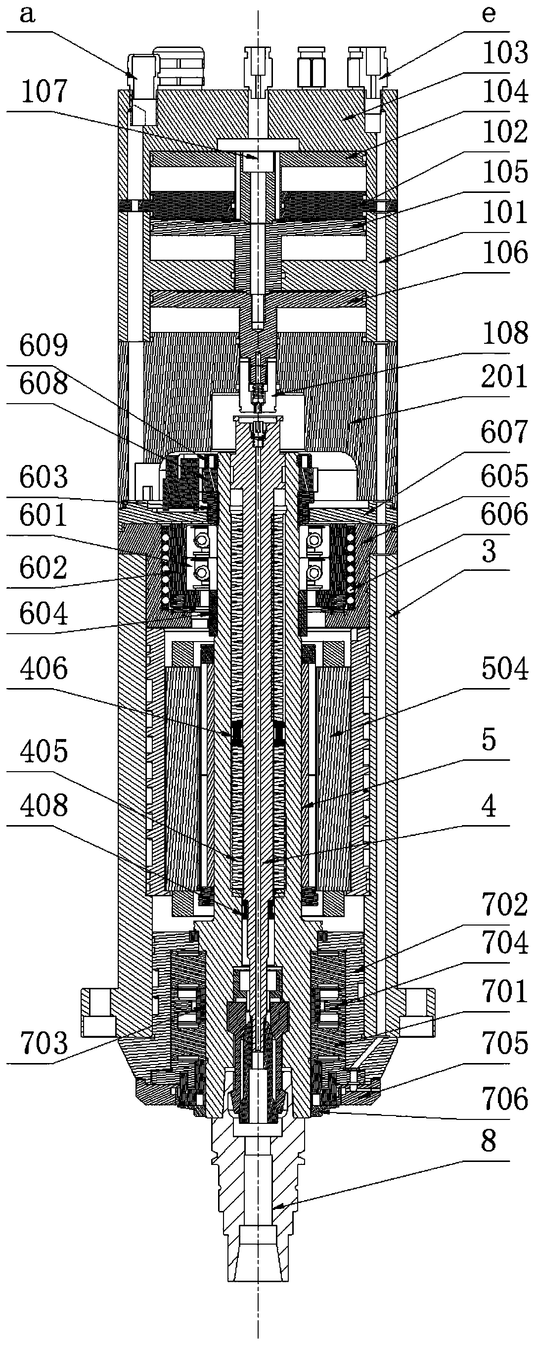
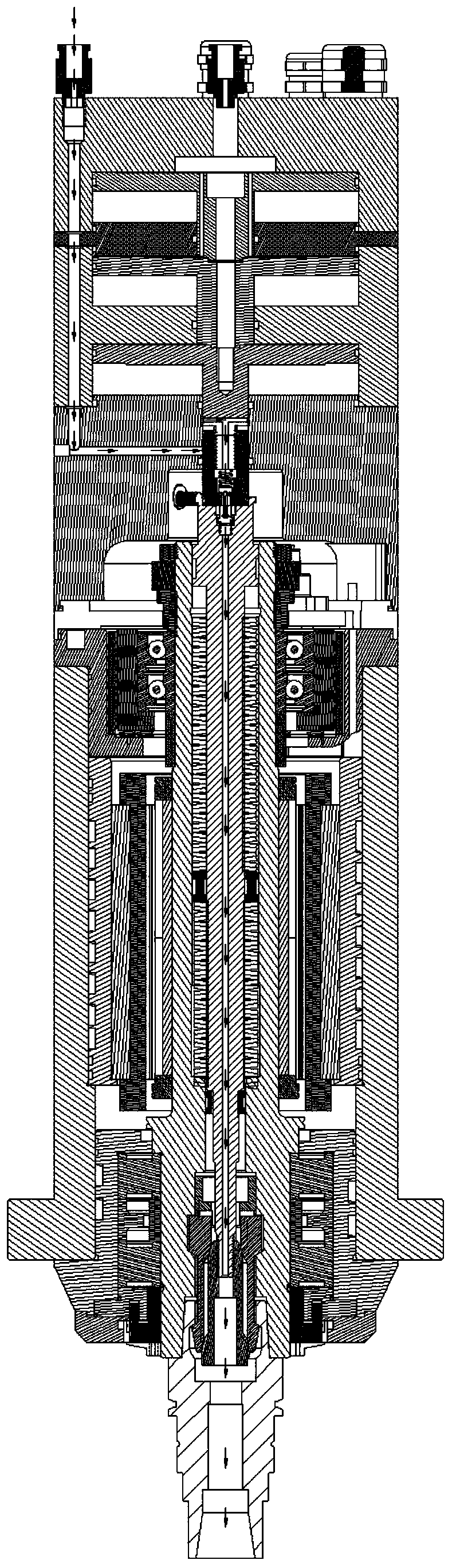
[0045] see Figure 1-16 , an electric spindle structure of a high-speed engraving machine, comprising a cylinder assembly 1, a back cover detection assembly 2, a steel cylinder 3, a pull rod assembly 4, a rotor assembly 5, a rear bearing assembly 6, a front bearing assembly 7 and a knife handle 8, and Cylinder assembly 1, back cover detection assembly 2, steel cylinder 3, tie rod assembly 4, rotor assembly 5, rear bearing assembly 6, front bearing assembly 7 an...


PUM


Abstract

The invention relates to the technical field of processing center equipment and discloses an electric spindle structure of a high-speed finish engraving machine. The electric spindle structure comprises an air cylinder assembly, a back cover detecting assembly, a steel cylinder, a pull rod assembly, a rotor assembly, a rear bearing assembly, a front bearing assembly and a knife handle, wherein theair cylinder assembly comprises a first air cylinder and an air cylinder shim; the air cylinder shim is positioned in an upper chamber of the first air cylinder and divides the upper chamber of the first air cylinder into two chambers; and an air passage independent of the air chamber of the air cylinder assembly is formed in the edge of the air cylinder assembly, passes through the edge and thecenter shaft of the back cover detecting assembly and then penetrates through the center shaft of the pull rod assembly to reach the inner conical surface end of the knife handle. The air cylinder shim is additionally mounted in the air cylinder assembly and is mounted between the first air cylinder and an air cylinder cover; compared with the structure that the air cylinder cover is directly connected with the first air cylinder, a piston chamber is additionally formed; and the space occupied by the entire air cylinder assembly is slightly increased, so that larger knife loosening force can be provided for the spindle within a limited space.

Description

technical field [0001] The invention relates to the technical field of machining center equipment, in particular to an electric spindle structure of a high-speed fine carving machine. Background technique [0002] The electric spindle is a combination of the machine tool spindle and the spindle motor. It is actually a set of components, including the shellless motor, the spindle, the bearing, the spindle unit shell, the built-in encoder, the cooling device, etc. The rotor of the motor is press-fitted. The method is integrated with the main shaft, and the main shaft is supported by the front and rear bearings. This kind of machine tool main shaft is directly driven by the built-in motor, which shortens the length of the main transmission chain of the machine tool to zero, and realizes the "zero transmission" of the machine tool. [0003] In the field of high-speed fine carving, it is necessary to continuously change the state of the tool clamping and releasing the tool. Due t...

Claims


Application Information

Patent Timeline
Patent Type & Authority Applications(China)
IPC IPC(8): B23B19/02
CPCB23Q1/70
Inventor 农乃昌李存杰
Owner 深圳市爱贝科精密工业股份有限公司
Why Eureka
Try Eureka