Clamping assembly for cutting tool film coating

A technology for clamping components and tools, applied in sputtering plating, ion implantation plating, gaseous chemical plating, etc., can solve the problems of low device work efficiency, tool sliding, low tool clamping tightness, etc. Work efficiency, increase cleaning process, improve usability

Inactive Publication Date: 2019-08-27
超力等离子技术(常州)有限公司
View PDF0 Cites 2 Cited by
  • Summary
  • Abstract
  • Description
  • Claims
  • Application Information

AI Technical Summary

Problems solved by technology

[0003] The structure of the existing clamping components is relatively simple, which cannot meet the complex use environment. First, multiple tools cannot be clamped at the same time, and the working efficiency of the device is low. Second, the tightness of the tool clamping is not high, and it cannot meet the requirements The size floating deviation within a certain range, third, the tool is susceptible to sliding due to the influence of external factors during the coating work, fourth, it does not adapt to the operating habits of the operator, and the working efficiency of the device is low, and fifth, the tools generated during the coating work There is no reasonable discharge channel and space for waste

Method used


Image

  • Clamping assembly for cutting tool film coating
  • Clamping assembly for cutting tool film coating

Examples


Embodiment Construction

[0015] The following will clearly and completely describe the technical solutions in the embodiments of the present invention with reference to the accompanying drawings in the embodiments of the present invention. Obviously, the described embodiments are only some, not all, embodiments of the present invention. Based on the embodiments of the present invention, all other embodiments obtained by persons of ordinary skill in the art without making creative efforts belong to the protection scope of the present invention.

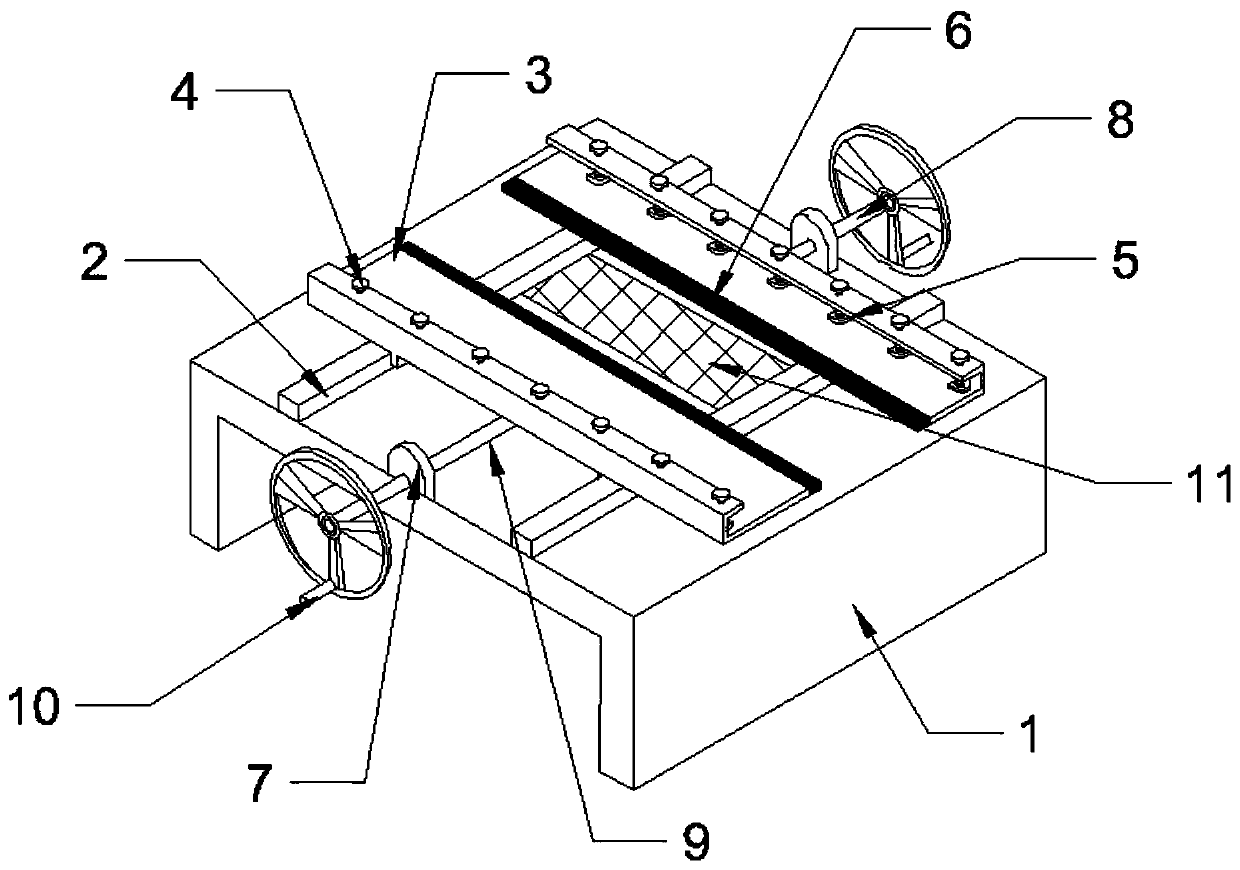
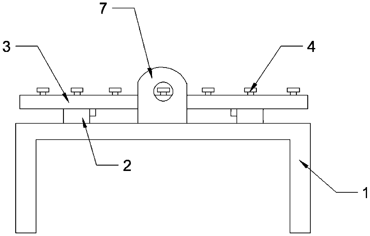
[0016] see Figure 1~2 , a clamping assembly for tool coating, including a mounting base 1, a guide rail 2, a clamping base 3, a fastening nut 4, a gasket 5, a limit bar 6, a screw mounting head 7, a wheel 8, Screw mandrel 9, rotating handle 10 and cleaning net 11; The installation base 1 is located at the bottom of the device, and the front side has a rectangular slot, and the top surface of the installation base 1 is fixedly connected with the bottom of the ...


PUM


Abstract

The invention discloses a clamping assembly for cutting tool film coating. The clamping assembly for the cutting tool film coating comprises a mounting base seat, a guide rail, a clamping bottom seat,a fastening nut, a spacer, a limiting strip, a screw rod mounting head, a wheel disc, a screw rod, a rotation handle and a cleaning net. The clamping assembly for the cutting tool film coating has the advantages that the bottom of the fastening nut is fixedly connected with a preset threaded hole in the clamping bottom seat, and therefore the effect that multiple cutting tools can be simultaneously clamped is achieved, and work efficiency of a device is improved; the spacer and the clamping bottom seat are fixedly connected, and therefore clamping tightness of the cutting tools is improved, and simultaneously size floating deviations in a certain range can be met; the outer end of the limiting strip is fixedly connected with the inner side of the clamping bottom seat, and therefore one-time complete implementation of film coating work is ensured; the bottom of the rotation handle is fixedly connected with an outer ring of a wheel disk, and therefore the clamping assembly for the cutting tool film coating adapts to use habits of operating personnel; the outer side of the cleaning net is fixedly connected with the top face of the mounting base seat, and therefore the shortcoming that due to the fact that waste is stacked on the device, a follow-up cleaning process is added is avoided.

Description

technical field [0001] The invention relates to a clamping assembly, in particular to a clamping assembly for tool coating, and belongs to the technical field of tool coating. Background technique [0002] With the rapid development of my country's machinery manufacturing industry, there are more and more difficult-to-machine materials, and new cutting technologies continue to emerge. In order to meet the above requirements and make cutting tools both cheap and superior in performance, coating tools should be the first choice. When the existing tools are used for coating processing, there is no professional fixture that can not only process multiple tools at the same time, but also take care of the uniformity of the coating layer of each tool. Therefore, a clamping tool for coating is needed components. [0003] The structure of the existing clamping components is relatively simple, which cannot meet the complex use environment. First, multiple tools cannot be clamped at t...

Claims


Application Information

Patent Timeline
Patent Type & Authority Applications(China)
IPC IPC(8): C23C14/50C23C16/458
CPCC23C14/50C23C16/4581
Inventor 李东奎
Owner 超力等离子技术(常州)有限公司
Why Eureka
Try Eureka