
Papermaking drying device based on air flow transformation

A drying device and airflow technology, applied in papermaking, papermaking, textiles and papermaking, etc., can solve the problems of uneven surface, affecting paper quality, affecting paper drying rate, etc., to increase drying speed, ensure quality, and dryness. roughly synchronized effect

Inactive Publication Date: 2019-08-27
夏德亮
View PDF7 Cites 0 Cited by
  • Summary
  • Abstract
  • Description
  • Claims
  • Application Information

AI Technical Summary

Problems solved by technology

[0003] At present, most of the existing drying parts are drying the wet pulp with a drying plate or an electric heating plate, and then making it into paper. However, in this form, the moisture in the pulp is dried into paper At the time, it is a physical evaporation process, the water in the pulp changes from a liquid state to a gaseous state, and in the process of gradually rising the gaseous water, it will eventually be intercepted by the cover plate, and the temperature of the cover plate is lower than that of the gaseous water vapor. Therefore, when the gaseous water vapor is cold, it will condense into small water droplets on the cover plate, and finally it will fall and drip on the made paper. Since the paper has not been completely dried and formed, dripping on it may cause the The surface of the paper made is uneven, which affects the drying rate of the paper, thus affecting the quality of the paper

Method used


Image

  • Papermaking drying device based on air flow transformation
  • Papermaking drying device based on air flow transformation
  • Papermaking drying device based on air flow transformation

Examples


Embodiment Construction

[0019] The following will clearly and completely describe the technical solutions in the embodiments of the present invention with reference to the accompanying drawings in the embodiments of the present invention. Obviously, the described embodiments are only some, not all, embodiments of the present invention. Based on the embodiments of the present invention, all other embodiments obtained by persons of ordinary skill in the art without making creative efforts belong to the protection scope of the present invention.

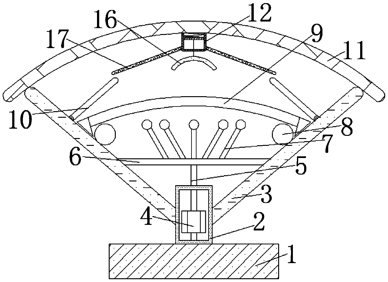
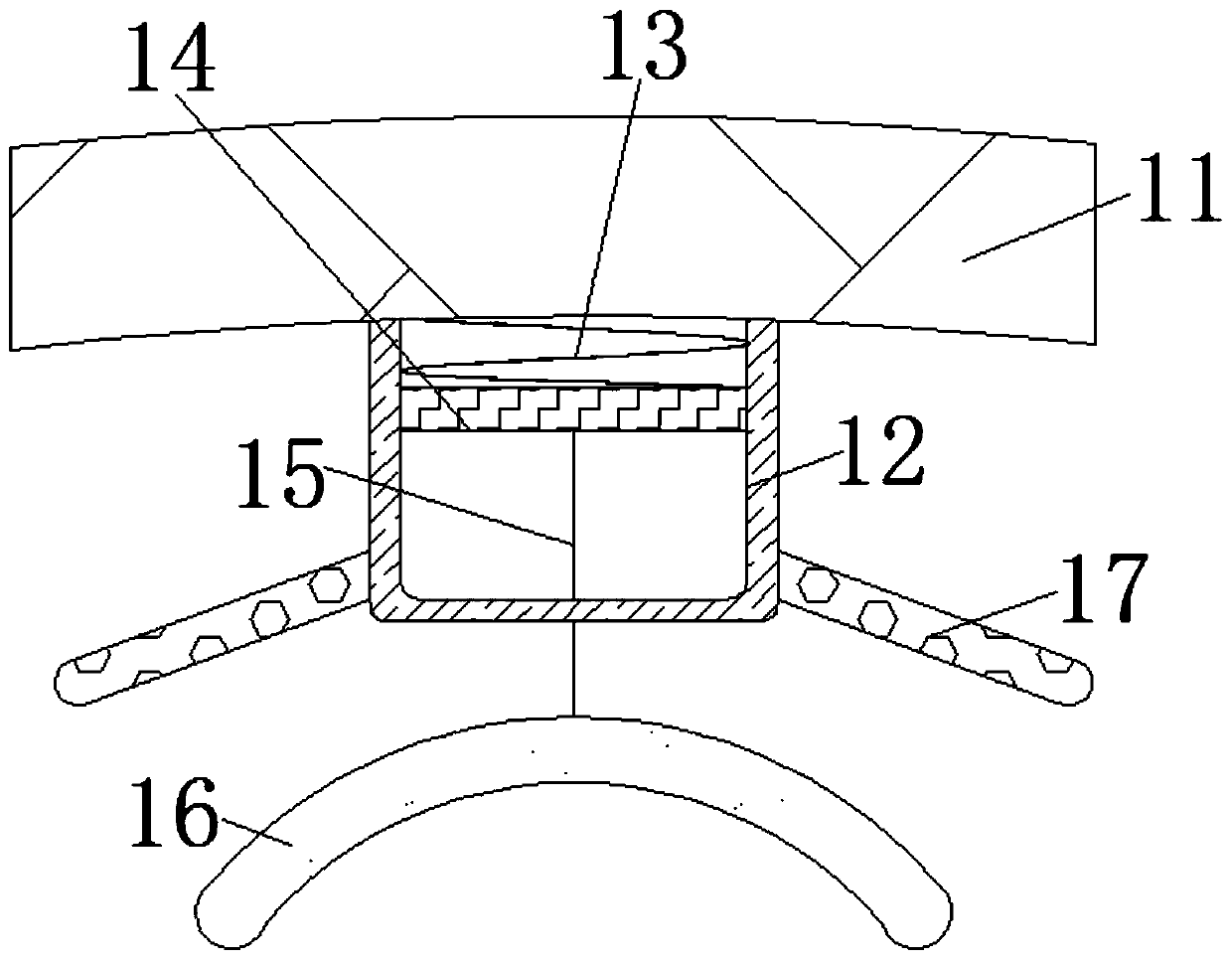
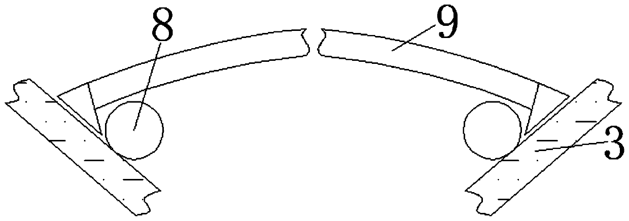
[0020] see Figure 1-3 , a paper-making drying device based on air flow conversion, including a base 1, a water storage tank 2 is fixedly installed on the upper surface of the base 1, the upper end of the water storage tank 2 penetrates and extends to the inside of the drying plate 3, and the outer side of the water storage tank 2 is covered with The middle part of the drying plate 3 and the water storage tank 2 is movably equipped with a rotating rod 5, and t...


PUM


Abstract

The invention relates to a papermaking drying device based on air flow transformation, which comprises a base, wherein a water tank is fixedly mounted on the upper surface of the base; the outer sideof the water tank is sleeved with drying plates; a rotating rod is movably mounted in the middle of the water tank; a turbine blade is fixedly mounted at the lower end of the rotating rod; and a rotating disc is fixedly mounted at the upper end, penetrating through and extending to the outside of the water tank, of the rotating rod. Water droplets dropping from a cover plate can be effectively blocked due to matched use of a sealing housing, a tension spring, a movable plate, a connecting rope, a heat return plate and corrugated strips; the water droplets cannot drop on paper being dried; situations such as an uneven surface of the paper due to dropping of the water droplets on the paper do not occur; the influence of the dropping of the water droplets on a drying rate of the paper is avoided; drying of paper pulp is accelerated indirectly; the production efficiency is improved; and at the same time, the quality of the made paper is further guaranteed.

Description

technical field [0001] The invention relates to the technical field of intelligent manufacturing, in particular to a papermaking drying device based on air flow conversion. Background technique [0002] The paper machine includes three main parts of forming, pressing and drying to complete the process, and is equipped with necessary finishing, coiling and transmission devices, as well as pulp supply, pulp and white water circulation, vacuum, ventilation and exhaust, broken paper Handling and lubrication, automatic control and other auxiliary systems, while the drying part is one of the very important components in the paper machine. [0003] At present, most of the existing drying parts are drying the wet pulp with a drying plate or an electric heating plate, and then making it into paper. However, in this form, the moisture in the pulp is dried into paper At the time, it is a physical evaporation process, the water in the pulp changes from a liquid state to a gaseous state...

Claims


Application Information

Patent Timeline
Patent Type & Authority Applications(China)
IPC IPC(8): D21F5/00
CPCD21F5/004
Inventor 夏德亮
Owner 夏德亮
Learn More