Electromechanical power regulation and control device

A power regulation and electromechanical technology, applied in the field of circuits, can solve problems such as heat-generating equipment, prone to arcing, friction loss, etc., to achieve automatic calibration, ensure signal current, and ensure stability.

Inactive Publication Date: 2019-08-27
ZHENGZHOU UNIV OF IND TECH
View PDF11 Cites 11 Cited by
  • Summary
  • Abstract
  • Description
  • Claims
  • Application Information

AI Technical Summary

Problems solved by technology

[0002] At present, equipment is usually a general term for material materials such as machinery, devices, and facilities that people need in production and life. Electromechanical equipment refers to equipment that uses mechanical and electronic technologies. An important part, the power supply of the electromechanical equipment is powered by the mains voltage, and the internal voltage converter of the electromechanical equipment is transformed to supply power for the electromechanical equipment. Because the low-voltage electromechanical equipment runs for too long, it is prone to heat and friction loss between the equipment, which will cause Increase the voltage output power loss of the internal voltage converter of the low-voltage electromechanical equipment, which means that the power supply of the electromechanical equipment is insufficient. Long-term operation is prone to arcing, causing fires, and causing unpredictable losses.

Method used


Image

  • Electromechanical power regulation and control device
  • Electromechanical power regulation and control device
  • Electromechanical power regulation and control device

Examples


Embodiment 1

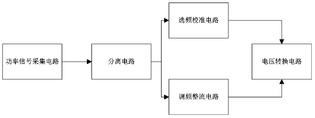
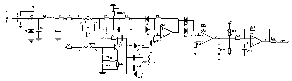
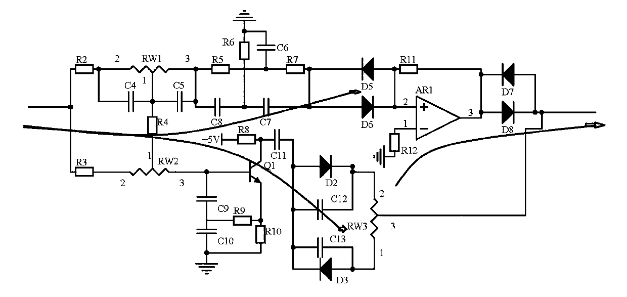
[0016] Embodiment 1, an electromechanical power control device, including a power signal acquisition circuit, a separation circuit, a frequency selection calibration circuit, a frequency modulation rectification circuit and a voltage conversion circuit, is characterized in that the power signal acquisition circuit uses a power acquisition model of AD8318 The device J1 collects the power signal of the power supply of the electromechanical equipment, uses the inductance L1, the capacitor C2, and the capacitor C3 to form a π-type filter circuit for filtering, and the separation circuit uses the variable resistor RW1, the variable resistor RW2, the capacitor C4, and the capacitor C5 to form a separation circuit. The signal is divided into two signals with the same frequency and different amplitudes, one is adjusted by the frequency selection calibration circuit, and the frequency selection circuit is composed of resistor R5-resistor R7 and capacitor C6-capacitor C8 to filter out a s...

Embodiment 2

[0019]Embodiment 2, on the basis of Embodiment 1, the voltage conversion circuit uses the operational amplifier AR2 to perform addition processing on the two signals to ensure that the compensation signal is consistent with the original power signal potential, and uses the operational amplifier AR5 and the variable resistor R16 and capacitor C14 form a voltage conversion circuit to convert the current signal into a voltage signal and output it, that is, the compensation signal for the power supply power of the electromechanical equipment. The compensation signal is used to overcome the insufficient power of the power supply of the electromechanical equipment. The non-inverting input terminal of the amplifier AR2 is connected to the contact 3 of the variable resistor RW3 and one end of the resistor R13, the inverting input terminal of the operational amplifier AR2 is connected to one end of the resistor R14, the other end of the resistor R14 is grounded, and the output terminal o...

Embodiment 3

[0020] Embodiment 3, on the basis of Embodiment 1, the power signal acquisition circuit adopts the model AD8318 power collector J1 to collect the power signal of the power supply of the electromechanical equipment, and uses the inductance L1, capacitor C2, and capacitor C3 to form a π-type filter circuit for filtering , the power supply terminal of the power collector J1 is connected to the power supply +5V and one end of the capacitor C1, the ground terminal of the power collector J1 is grounded, and the output terminal of the power collector J1 is connected to the other end of the capacitor C1, one end of the inductor L1, one end of the capacitor C2 and the stabilizer The negative pole of the pressure tube D1, the positive pole of the Zener tube D1 are grounded, the other end of the capacitor C2 is grounded, the other end of the inductor L1 is connected to the resistor R1, one end of the capacitor C3, the other end of the capacitor C3 is grounded, and the other end of the resi...


PUM


Abstract

The invention discloses an electromechanical power regulation and control device. The electromechanical power regulation and control device comprises a power signal acquisition circuit, a separation circuit, a frequency selection calibration circuit, a frequency modulation rectification circuit and a voltage conversion circuit; the power signal acquisition circuit acquires a power signal of a power supply of electromechanical equipment by using a power acquirer J1 with a model number of AD8318; the separation circuit comprises a variable resistor RW1, a variable resistor RW2, a capacitor C4 and a capacitor C5, and divides the signal into two paths of signals with the same frequency and different amplitudes; the frequency selection circuit comprises a resistor R5, a resistor R7, a capacitorC6 and a capacitor C8, and screens out the signal with the single frequency; the frequency modulation rectification circuit comprises a triode Q1, a capacitor C9 and a capacitor C11, and performs frequency modulation on the signal; and finally, the voltage conversion circuit comprises an operational amplifier AR5, a variable resistor R16 and a capacitor C14, converts a current signal into a voltage signal and then outputs the voltage signal. The value of a power compensation signal of the power supply of the electromechanical equipment is automatically adjusted according to the power signal of the power of the power supply of the electromechanical equipment.

Description

technical field [0001] The invention relates to the field of circuit technology, in particular to an electromechanical power regulating device. Background technique [0002] At present, equipment is usually a general term for material materials such as machinery, devices, and facilities that people need in production and life. Electromechanical equipment refers to equipment that uses mechanical and electronic technologies. An important part, the power supply of the electromechanical equipment is powered by the mains voltage, and the internal voltage converter of the electromechanical equipment is transformed to supply power to the electromechanical equipment. Because the low-voltage electromechanical equipment runs for too long, it is prone to heat and friction loss between the equipment, which will cause Increase the voltage output power loss of the internal voltage converter of the low-voltage electromechanical equipment, which means that the power supply of the electromec...

Claims


Application Information

Patent Timeline
Patent Type & Authority Applications(China)
IPC IPC(8): H02M1/00
CPCH02M1/00H02M1/0003
Inventor 张国栋祁瑞敏
Owner ZHENGZHOU UNIV OF IND TECH
Why Eureka
Try Eureka