Disinfection cabinet

A disinfection cabinet and liner technology, which is applied in the field of disinfection cabinets, can solve the problems of cabinet rot, mildew, ineffective volatilization, etc., and achieve the effect of maintaining aesthetics, simple structure, and preventing leakage

Active Publication Date: 2019-08-30
NINGBO FOTILE KITCHEN WARE CO LTD
View PDF10 Cites 2 Cited by
  • Summary
  • Abstract
  • Description
  • Claims
  • Application Information

AI Technical Summary

Problems solved by technology

In this way, the water vapor will gather inside the cabinet and cannot be effectively volatilized. After long-term use, it will easily cause the cabinet to rot and mildew
In addition, the front surface of the existing disinfection cabinet is generally a handle that matches the glass panel, such as the Chinese invention patent "Front Panel Assembly and Disinfection Device with the Front Panel Assembly" with the patent number ZL200710019850.6 (authorized

Method used


Image

  • Disinfection cabinet
  • Disinfection cabinet
  • Disinfection cabinet

Examples


Embodiment 1

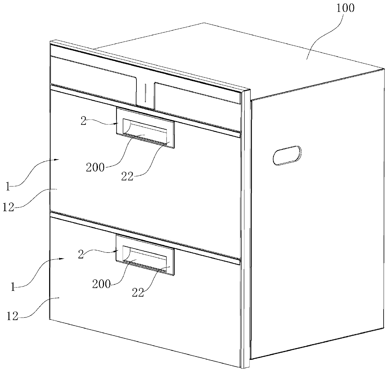
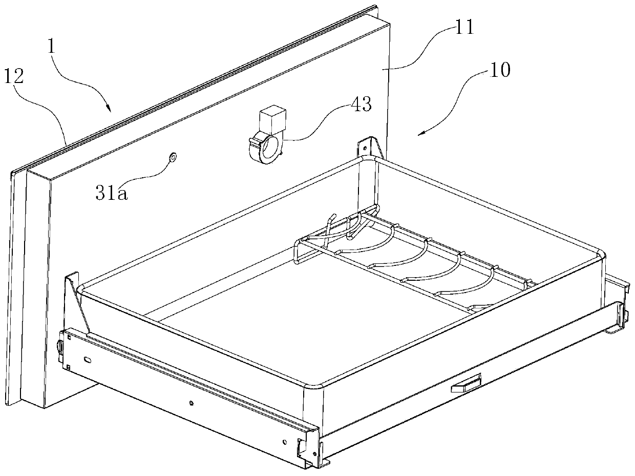
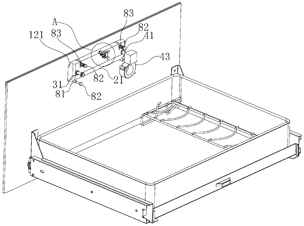
[0036] Such as Figure 1-8As shown, a disinfection cabinet includes a cabinet body 1, the front of which is open and its inner cavity is the inner container of the disinfection cabinet. In this embodiment, two drawers 10 are arranged above and below the inner container, and the drawer panels of each drawer 10 respectively constitute the door body 1 of the disinfection cabinet and cover the opening of the inner container. Each door body 1 includes a box-shaped door frame 11 and a panel 12, the panel 12 covers the opening of the door frame 11, and the panel 12 is provided with an installation opening 121, and a handle 2 is embedded in the installation opening 121, The panel 12 and the door frame 11 enclose a space 10 a capable of accommodating the handle 2 , and the handle 2 includes a handle body 21 and a handle panel 11 arranged on the front face of the handle body 21 .

[0037] The above-mentioned handle 2 is provided with an air intake mechanism and an exhaust mechanism, wh...

Embodiment 2

[0044] Such as Figure 9 with Figure 10 As shown, the difference from Embodiment 1 is that in this embodiment, an air inlet 311 is provided on the wall of the inlet end of the intake pipe 31, and an exhaust hole 411 is provided on the wall of the exhaust end of the exhaust pipe 41. , the first blocking member 32 and the second blocking member 42 are sleeves fixed on the handle 2, and the intake end of the intake pipe 31 and the exhaust end of the exhaust pipe 41 can be respectively inserted into the corresponding sleeves, And can move back and forth respectively relative to the corresponding sleeve, so that the air intake hole 311 on the air intake pipe 31 and the exhaust hole 411 on the exhaust pipe 41 can be blocked or opened by the side wall of the sleeve respectively.

Embodiment 3

[0046] Such as Figures 11-14 As shown, the difference from Embodiment 1 is that the middle part of the turning linkage 52 in this embodiment is fixed with a roller bar 5222 extending perpendicularly to the turning linkage 52 , and the junction between the roller bar 5222 and the turning linkage 52 The above-mentioned shaft hole 520 is formed at the position, and the free end of the roller rod 5222 is formed with a U-shaped groove 5223, the above-mentioned roller 5221 is installed in the U-shaped groove 5223, and the above-mentioned contact surface 61 is arranged on the top surface of the first connecting member 6 , and the free end of the first connecting member 6 has a stopper 63 extending upwards, and when the roller 5221 abuts against the contact surface 61 on the first connecting member 6 , the stopper 63 is limited to the rear side of the roller 5221 .


PUM


Abstract

The invention relates to a disinfection cabinet. The disinfection cabinet comprises a liner and a door body, wherein the door body covers an opening of the liner and is provided with a handle, the door body comprises a door frame and a panel, the panel covers an opening of the door frame, a mounting hole for inserting the handle is opened in the panel, the panel and the door frame enclose a spacecapable of accommodating the handle, the handle is provided with an air intake mechanism and an air exhaust mechanism, the air intake mechanism includes an air intake pipe and a first blocking member,an air intake end of the air intake pipe can communicate with the outside, an air outlet end of the air intake pipe communicates with the liner, the first blocking member is fixed on the handle, theair exhaust mechanism includes an air exhaust pipe and a second blocking member, an air exhaust end of the air exhaust pipe can communicate with the outside, an air outlet end of the air exhaust pipecommunicates with the liner, and the second blocking member is fixed on the handle. The disinfection cabinet in the invention can avoid rotting and mildewing of the cabinet caused by accumulation of externally discharged water vapor in the cabinet by means of air inlet and exhaust from the front. Moreover, the air intake mechanism and the air exhaust mechanism have simple structures and can effectively prevent the leakage of disinfecting gas.

Description

technical field [0001] The invention relates to the field of household appliances, in particular to a disinfection cabinet. Background technique [0002] With the improvement of living standards, tableware disinfection cabinets have gradually entered people's daily lives. Heating is a commonly used technical method for disinfection cabinets. Generally, at the end of disinfection, high-temperature sterilization and rapid decomposition of ozone are achieved through heating. During the heating process, the water on the surface of tableware and in the inner container is evaporated into water vapor. For this reason, it is necessary to discharge ozone, water vapor, etc. in the end stage of disinfection. The exhaust system in the existing disinfection cabinet is generally arranged on the back of the disinfection cabinet. ) of the Chinese invention patent discloses a disinfection cabinet, the upper right side of the back of the cabinet is provided with an exhaust port, the inner bo...

Claims


Application Information

Patent Timeline
IPC IPC(8): A61L2/26A61L2/20A61L101/10
CPCA61L2/202A61L2/26
Inventor 袁柯铭黄鹏
Owner NINGBO FOTILE KITCHEN WARE CO LTD
Why Eureka
Try Eureka