Eureka AIR delivers breakthrough ideas for toughest innovation challenges, trusted by R&D personnel around the world.

Dust gathering structure and device applying same

A technology of dust and air flow, which is applied in the field of dust treatment, can solve the problems of reducing the application popularity of dust removal devices, large-scale, complex structure, and health hazards of on-site personnel, and achieves the advantages of easy preparation, compact and effective structure, and improved dust removal effect Effect

Pending Publication Date: 2019-08-30
衡水圣凯环保设备有限公司
View PDF0 Cites 0 Cited by
  • Summary
  • Abstract
  • Description
  • Claims
  • Application Information

AI Technical Summary

Problems solved by technology

[0002] In various processing and on-site construction industries, the generation of dust is extremely common, which not only poses a health hazard to on-site personnel, but also adversely affects the development of work and pollutes the air
[0003] The existing dust removal equipment or devices generally have the characteristics of large-scale and complex structures; while in the processing or construction site, the dust point is flexible and changeable, and the dust source is often concentrated in one point or several points; therefore, the existing dust removal device Less applicable in this usage scenario
[0004] In addition, the existing dust collection and dust removal structure mostly adopts the method of filter element adsorption, which purifies the air by filtering and absorbing the dust airflow; this way, the damage to the filter element is relatively high, and the treatment of the polluted filter element causes secondary pollution, thus further reducing Improve the application popularity of dust removal devices in processing and construction sites

Method used


Image

  • Dust gathering structure and device applying same
  • Dust gathering structure and device applying same
  • Dust gathering structure and device applying same

Examples


Embodiment 1

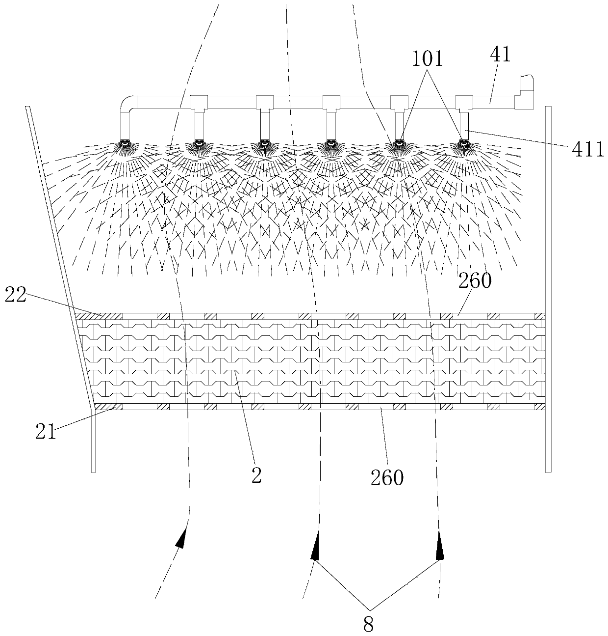
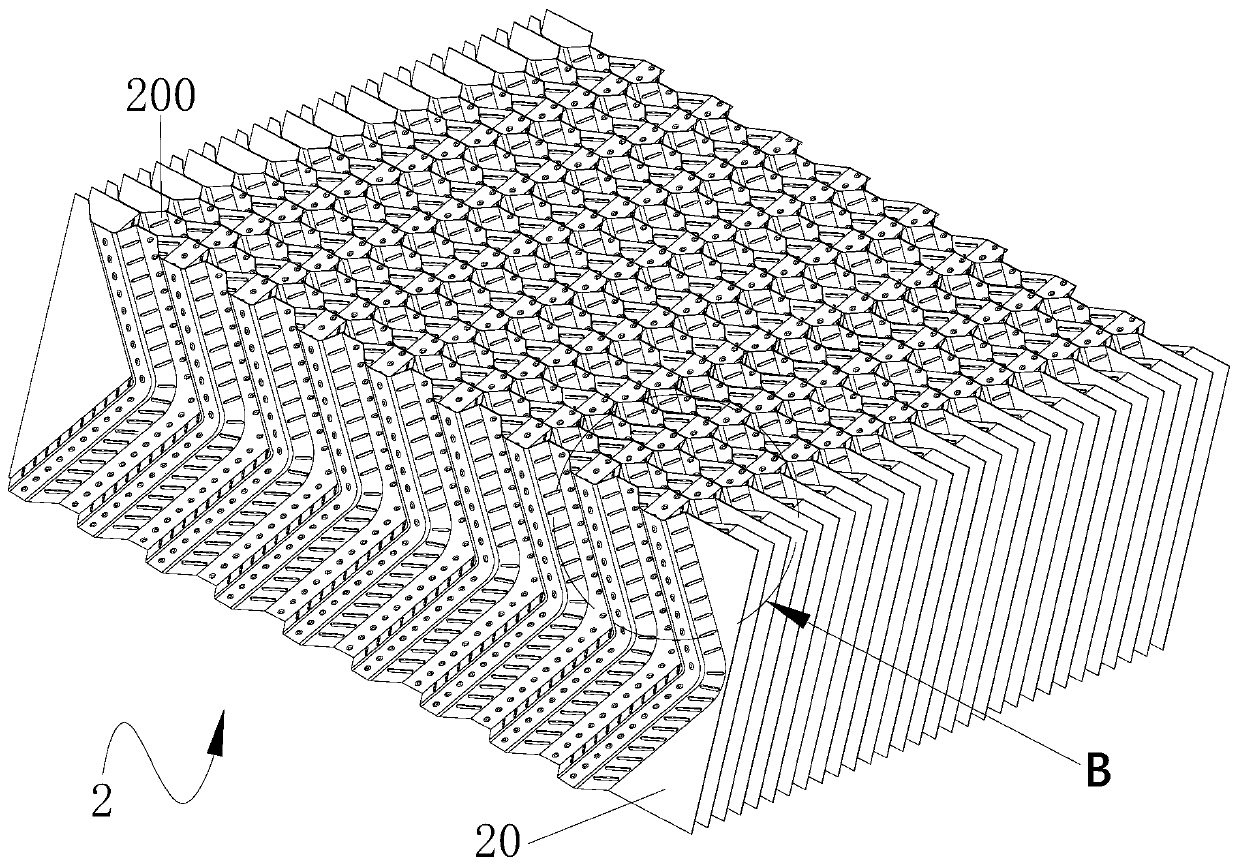
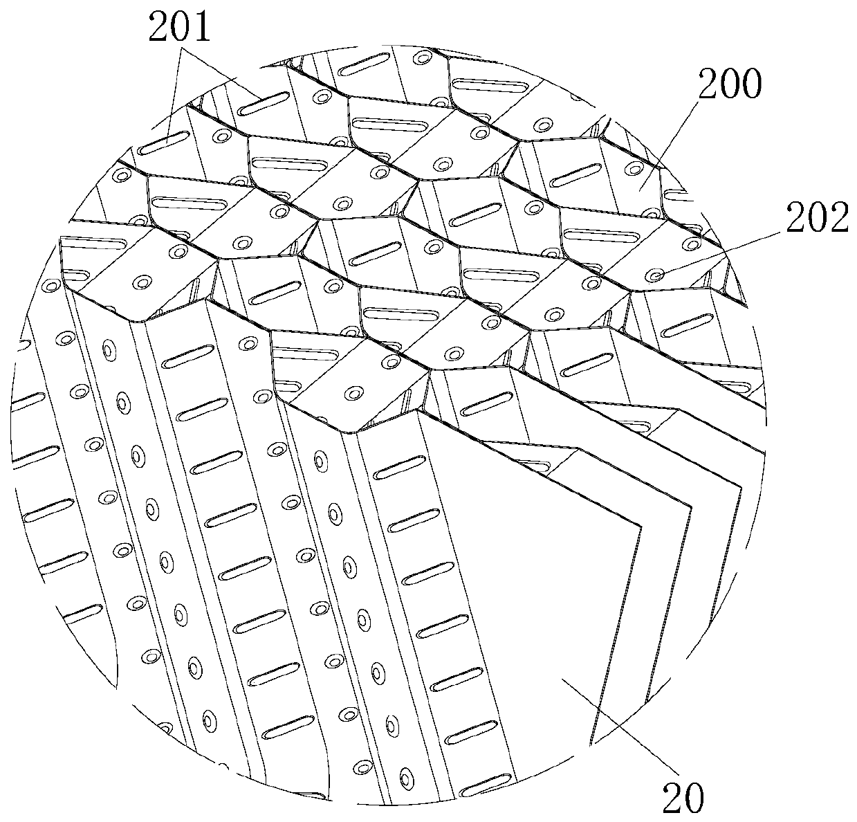
[0052] This embodiment relates to a dust collection structure, which is suitable for the miniaturization application of the dust removal structure, and can save the loss of the filter material in the dust removal process. The dust collection structure is arranged on the bottom-up airflow path containing dust, and includes a water application unit and an attachment unit. The water application unit accepts the external water supply and releases the water curtain. The water curtain is sprayed and can cover the air flow; the attachment unit is set under the water application unit to undertake the whereabouts of the water in the water curtain, and the attachment unit is covered with zigzag channels. The hole constitutes the conduction of the attachment unit in the airflow direction.

[0053] Based on the above general structural principles, an exemplary structure of the dust collection structure of this embodiment is as follows: figure 1 As shown, the structure is arranged on the ...

Embodiment 2

[0066] This embodiment relates to a device for collecting dust, an exemplary structure of which is as follows Image 6 and Figure 7 shown. The device includes a cabinet body 3, and an air induction unit and a water supply unit arranged in the cabinet body 3, and also includes the dust collection structure described in Embodiment 1; Air inlet 301.

[0067] The device for dust collection in this embodiment mainly includes a cabinet body 3 , an air induction unit, a water supply unit, a water application unit, an attachment unit 2 and a water blocking and dust suppression unit 6 .

[0068] In order to facilitate the mobile use of the device, the device adopts a removable design. For example, three or four rollers 305 can be installed at the bottom of the cabinet body 3 . And in order to be suitable for the airflow 8 introduction of dust source, as Image 6 As shown in , the air inlet 301 is opened on one side of the cabinet body 3 .

[0069] like Figure 7 As shown, the a...


PUM


Abstract

The invention provides a dust gathering structure and a device applying the same. The dust gathering structure provided by the invention is arranged on a path where bottom-up airflow advances and which contains dust. The structure comprises a water applying unit and an attachment unit. The water applying unit receives external water source supply and releases water curtain, wherein the water curtain is of a spraying shape and can cover the airflow; the attachment unit is arranged below the water applying unit for bearing the fall of water in the water curtain, and is covered with winding porous channels forming the conduction of the attachment unit in the direction of the airflow. The dust gathering structure provided by the invention is applicable to miniaturization of dust removal structures, and can reduce the loss of filter materials in the process of dust removal.

Description

technical field [0001] The invention relates to the technical field of dust treatment, in particular to a dust collection structure. The invention also relates to a device to which the structure is applied. Background technique [0002] In various processing and on-site construction industries, the generation of dust is extremely common, which not only poses a health hazard to on-site personnel, but also adversely affects the development of work and pollutes the air. [0003] The existing dust removal equipment or devices generally have the characteristics of large scale and complex structure; while in the processing or construction site, the dust point is flexible and changeable, and the dust source is often concentrated in one point or several points; therefore, the existing dust removal device The applicability is low in this usage scenario. [0004] In addition, the existing dust collection and dust removal structure mostly adopts the method of filter element adsorptio...

Claims


Application Information

Patent Timeline
IPC IPC(8): B01D50/00
CPCB01D50/40
Inventor 施福香田福院李立国
Owner 衡水圣凯环保设备有限公司
Why Eureka
Eureka Blog
Learn More