Plastic particle production system

A production system and technology for plastic granules, applied in the field of plastic granule production equipment, can solve problems such as uneven size of plastic strips

Inactive Publication Date: 2019-08-30
CHONGQING JINGBANG HIGH MOLECULAR MATERIAL CO LTD
View PDF6 Cites 12 Cited by
  • Summary
  • Abstract
  • Description
  • Claims
  • Application Information

AI Technical Summary

Problems solved by technology

[0004] The present invention intends to provide a plastic granule production system to solve the problem in the prior art that the plastic strips are easily pulled by gravity to cause uneven sizes

Method used


Image

  • Plastic particle production system
  • Plastic particle production system
  • Plastic particle production system

Examples


Embodiment 1

[0028] Embodiment 1 is basically as follows:

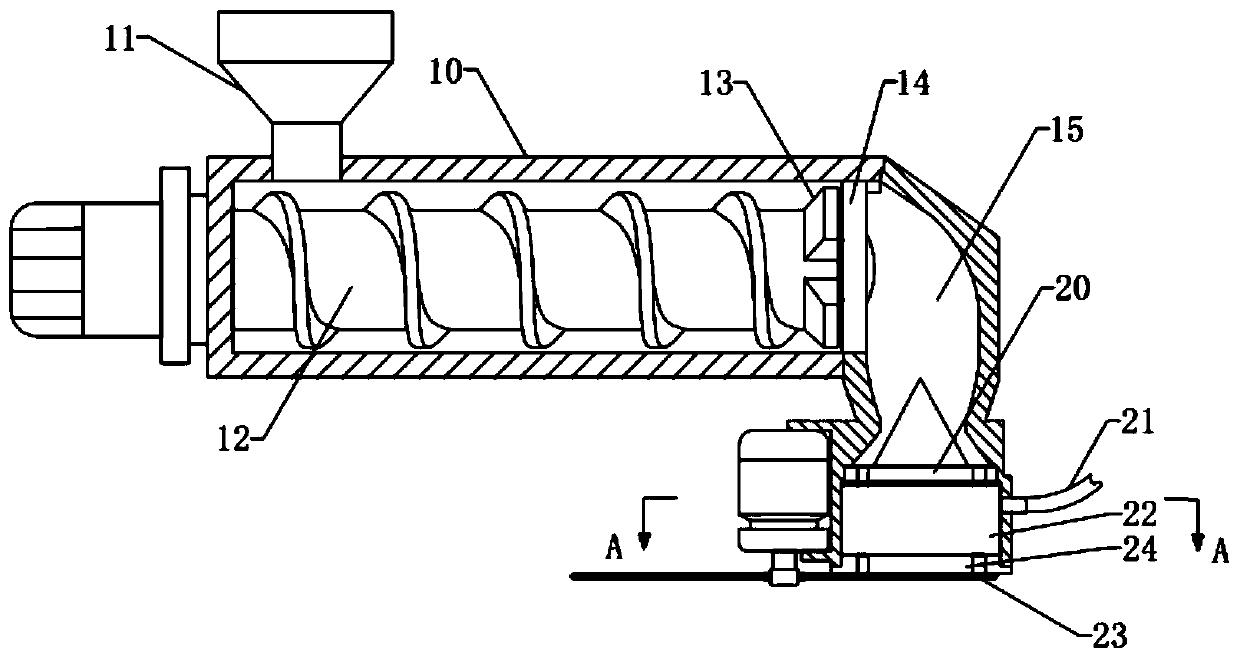
[0029] Plastic pellet production systems such as figure 1 As shown, an extruder is included, and the extruder includes a housing 10, a screw 12 and a die 20, the left end of the housing 10 is provided with a feed hopper 11, and the inner wall of the housing 10 is provided with an electric heating wire for heating the raw materials to form a molten state . The screw 12 is located within the housing 10 . An extruding motor is fixed outside the housing 10 , and the power shaft of the extruding motor passes through the housing 10 and is fixed with the screw rod 12 . The screw 12 rotates under the drive of the extrusion motor to stir the raw materials and transport them to the right.

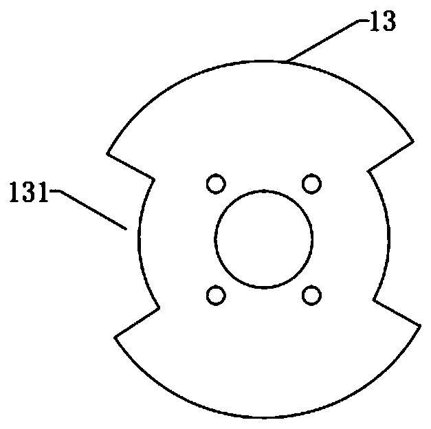
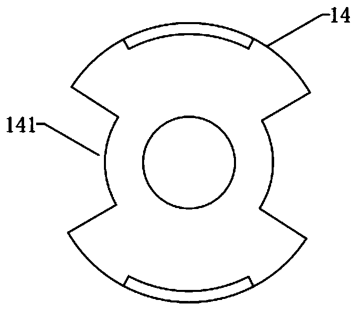
[0030] The right end of the screw rod 12 is a discharge end, and an intermittent discharge mechanism is provided outside the discharge end. The intermittent discharge mechanism includes a control plate 13 and a baffle plate 14. The control plate 13 an...

Embodiment 2

[0035] The difference from Embodiment 1 is that, as Figure 5 As shown, a cooling pipe 30 is provided below the cutting knife 23 , and a receiving hopper 31 is provided on the cooling pipe 30 . The receiving hopper 31 can catch the cut plastic particles and the cooling water flowing out from the rapid cooling chamber 22 and enter the cooling pipe 30 . In order to further cool the plastic particles, the left end of the cooling pipe 30 is also connected with a water supply pipe 21, and a cooling motor is fixed outside the left end of the cooling pipe 30, and the output shaft of the cooling motor extends into the cooling pipe 30 and is connected with an impeller. Driven by the cooling motor, the impeller transports the cooling water supplied by the water supply pipe 21 to the right, and mixes with the plastic particles to further cool the plastic particles. In order to enable the plastic particles to roll repeatedly in the cooling pipe 30 to accelerate cooling, a helical baffle ...


PUM


Abstract

The invention relates to the technical field of plastic particle production equipment, in particular to a plastic particle production system. The plastic particle production system comprises an extruding machine and a cutter; and the extruding machine comprises a shell, a screw and a mouth die, the mouth die is provided with extruding die holes, the screw is located in the shell, and the mouth dieis located outside the discharging end of the screw. The plastic particle production system is characterized in that the mouth die is vertically installed, and a quick cooling cavity is arranged under the mouth die and connected with a water supplying pipe; a limiting plate is fixed to the lower end of the quick cooling cavity and provided with constraint holes, and the constraint holes correspond to the extruding die holes and are in clearance fit with plastic strips; the cutter is located below the limiting plate; and an intermittent discharging mechanism is arranged between the dischargingend of the screw and the mouth die, the cutter conducts cutting during the non-discharging period, and a cooling pipe is arranged below the cutter and can further cool plastic particles. According tothe scheme, the plastic strips extruded out from the mouth die can be quickly cooled and formed, and the problem that in the prior art, the sizes of the plastic strips are not uniform due to gravitypulling is solved.

Description

technical field [0001] The invention relates to the technical field of plastic particle production equipment, in particular to a plastic particle production system. Background technique [0002] In the current production system of plastic pellets, the extruder extrudes the molten polymer from the die through the screw. After forming, the plastic strip needs to be cut, and the cutting method is divided into cold cutting and hot cutting. The hot cutting method is to cut the molten plastic strip directly at the die, and the cold cutting method is generally to cut the plastic strip after being cooled by water in a long cooling tank. [0003] However, since the plastic strip just formed at the die is still in a molten state, and the die is installed vertically to discharge material horizontally, no matter hot cutting or cold cutting, the newly formed part at the die will be pulled by the gravity of the plastic strip itself, which may easily cause the size of the plastic strip to...

Claims


Application Information

Patent Timeline
Patent Type & Authority Applications(China)
IPC IPC(8): B29B9/06B29B13/04
CPCB29B9/06B29B13/045
Inventor 王孝海
Owner CHONGQING JINGBANG HIGH MOLECULAR MATERIAL CO LTD
Why Eureka
Try Eureka