Hydrogen energy power generation system of metal hydrogen storage material

A technology for hydrogen storage materials and power generation systems, which is applied to machines/engines, steam engines, mechanical equipment, etc., can solve the problems of small generator power generation, low system energy conversion rate, limited promotion value, etc., and achieve economic benefits. , the effect of energy saving and emission reduction economic benefits

Pending Publication Date: 2019-08-30
SHANGHAI KELAIPU ENERGY TECH CO LTD
View PDF6 Cites 1 Cited by
  • Summary
  • Abstract
  • Description
  • Claims
  • Application Information

AI Technical Summary

Problems solved by technology

This utility model patent can convert air energy into kinetic energy to drive the generator set to rotate. However, due to the energy consumption of the cooler condensation, the energy conversion rate of the system becomes lower, and the generator generates less power, so the actual promotion value is limited.

Method used


Image

  • Hydrogen energy power generation system of metal hydrogen storage material
  • Hydrogen energy power generation system of metal hydrogen storage material
  • Hydrogen energy power generation system of metal hydrogen storage material

Examples


Embodiment 1

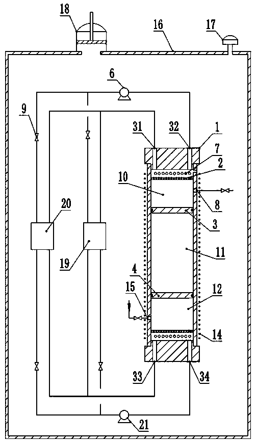
[0027] Metal hydrogen storage material hydrogen power generation system of the present invention such as figure 1 As shown, it includes a generator cylinder 1 , a heat accumulator 19 and a cold accumulator 20 . The generator cylinder 1 includes an upper end cover, a lower end cover and a cylinder body. The cylinder body is provided with a nitrogen gas inlet 15 and a nitrogen gas outlet 8. A generator coil 14 is wound outside the cylinder body, and the generator coil is connected to an external grid. The interior of the cylinder is provided with an upper piston 3 and a lower piston 4 of a permanent magnet structure, and the upper piston and the lower piston divide the cylinder into a telescopic upper hydrogen chamber 10 , a nitrogen chamber 11 and a lower hydrogen chamber 12 . The upper end cover is provided with an upper hydrogen outlet 31 and an upper hydrogen inlet 32 ​​, and the lower end cover is provided with a lower hydrogen outlet 33 and a lower hydrogen inlet 34 . The...

Embodiment 2

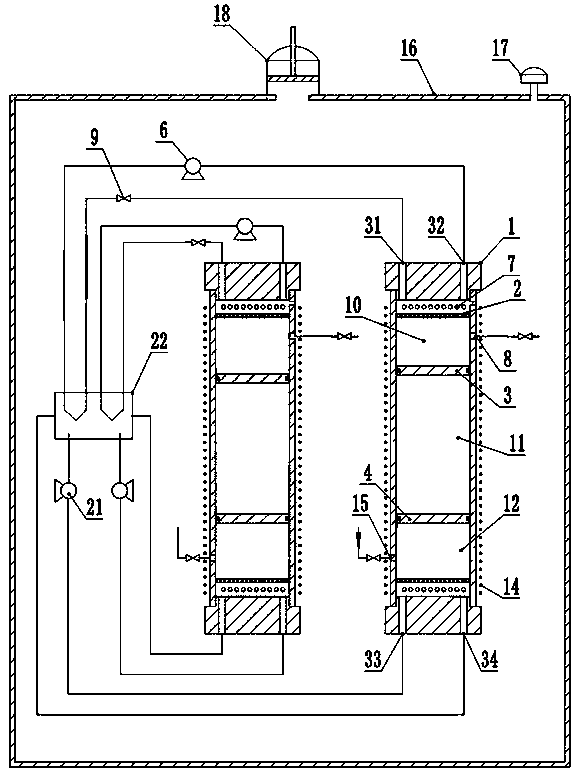
[0043] Another embodiment of the present invention is as figure 2 As shown, two generating cylinders 1 and a heat exchange center 22 are included. The upper hydrogen outlet 31 of the two generator cylinders 1 is connected to the heat exchange center 22, the connecting pipeline is provided with a valve, the heat exchange center 22 is connected to the upper hydrogen inlet 32 ​​through the upper hydrogen circulation pump 6, and the outlet pipeline of the heat exchange center 22 is provided with Valve 9. The lower hydrogen outlet 33 is connected to the heat exchange center 22, the connecting pipeline is provided with a valve, the heat exchange center 22 is connected to the lower hydrogen inlet 34 through the lower hydrogen circulation pump 21, and the outlet pipeline of the heat exchange center 22 is provided with a valve 9. Other structures of this embodiment are the same as those of Embodiment 1.

[0044] Two sets of generator cylinder structure are adopted, and the working p...

Embodiment 3

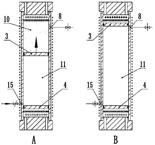
[0048] In another embodiment of the present invention, only the hydrogen absorption and desorption conditions of the upper and lower metal hydrogen storage materials are changed, and other structures and working principles are the same as those in Embodiment 2.

[0049] In this embodiment, the hydrogen absorption pressure of the upper metal hydrogen storage material is 0.1MPa, the hydrogen absorption temperature is 20°C, the hydrogen release pressure is 0.025MPa, and the hydrogen release temperature is -20°C. The hydrogen absorption pressure of the lower metal hydrogen storage material is 0.02MPa, the hydrogen absorption temperature is -18°C, the hydrogen release pressure is 0.11MPa, and the hydrogen release temperature is 18°C. The heat is balanced through the internal heat exchange of the heat exchange center 22 .


PUM


Abstract

The invention relates to a hydrogen energy power generation system of a metal hydrogen storage material. The hydrogen energy power generation system comprises at least one power generation cylinder, aheat accumulator and a regenerator, wherein a power generation coil is wound outside a cylinder body of the power generation cylinder, an upper piston and a lower piston with a permanent magnet structure are arranged inside the cylinder body, and the upper piston and the lower piston divide the cylinder body into an upper hydrogen chamber, a nitrogen chamber and a lower hydrogen chamber which aretelescopic. The upper part of the upper hydrogen chamber is provided with a grating, the upper part of the grating is provided with the metal hydrogen storage material, the lower part of the lower hydrogen chamber is provided with a grating, and the lower part of the grating is provided with the metal hydrogen storage material. An upper hydrogen outlet is connected to the heat accumulator and theregenerator, and the heat accumulator and the regenerator are connected to an upper hydrogen inlet. A lower hydrogen outlet is connected to the heat accumulator and the regenerator, and the heat accumulator and the regenerator are connected to a lower hydrogen inlet. According to the hydrogen energy power generation system, through the power generation cylinder internally provided with the upperpiston and the lower piston of the movable permanent magnet structure, hydrogen is used as a working medium, the power generation coil wound outside the cylinder body is enabled to generate electricity, the energy of the nature is fully utilized, energy conservation and emission reduction are facilitated, and economic benefits are created.

Description

technical field [0001] The invention belongs to the technical field of energy comprehensive utilization, and relates to a hydrogen energy power generation system of a metal hydrogen storage material. Background technique [0002] The natural world is full of unlimited energy at normal temperature, such as air and sea water, which have potential for development. Most of the energy on the earth comes from the sun. In today's increasingly scarce energy sources, new renewable, green and clean power generation technologies are increasingly valued. Among new energy sources, hydropower and wind power generation technologies are widely used and the technologies are relatively mature. The development potential of hydropower is not great, and the wind power is too scattered, so it can only be used in some specific areas, and the investment of hydropower and wind power generation devices is very large, covering a large area. Air energy has gradually entered people's field of vision. ...

Claims


Application Information

Patent Timeline
Patent Type & Authority Applications(China)
IPC IPC(8): F03G7/00F01K27/00F01B29/10F01B23/10
CPCF01B23/10F01B29/10F01K27/00F03G7/005
Inventor 贾鹏
Owner SHANGHAI KELAIPU ENERGY TECH CO LTD
Why Eureka
Try Eureka