
Shaftless fan and air conditioner

A fan, shaftless technology

Pending Publication Date: 2019-08-30
GD MIDEA AIR-CONDITIONING EQUIP CO LTD +1
View PDF0 Cites 0 Cited by
  • Summary
  • Abstract
  • Description
  • Claims
  • Application Information

AI Technical Summary

Problems solved by technology

[0002] At present, in people's daily life, the fan has become a relatively common heat dissipation tool. In particular, in the process of using the air conditioner, it has become a common driving method to discharge the cold or hot air from the air conditioner through the fan to the room. In the prior art, the fans of the existing air conditioners all adopt a motor with a drive shaft and a structure with multiple blades at one end of the drive shaft. However, due to structural limitations, it is easy to cause backflow loss at the blade root and blade tip clearance loss, which affects ventilation efficiency.

Method used


Image

  • Shaftless fan and air conditioner
  • Shaftless fan and air conditioner
  • Shaftless fan and air conditioner

Examples


Embodiment Construction

[0049] In order to understand the above-mentioned purpose, features and advantages of the present invention more clearly, the present invention will be further described in detail below in conjunction with the accompanying drawings and specific embodiments. It should be noted that, in the case of no conflict, the embodiments of the present application and the features in the embodiments can be combined with each other.

[0050] In the following description, many specific details are set forth in order to fully understand the present invention. However, the present invention can also be implemented in other ways different from those described here. Therefore, the protection scope of the present invention is not limited by the specific details disclosed below. EXAMPLE LIMITATIONS.

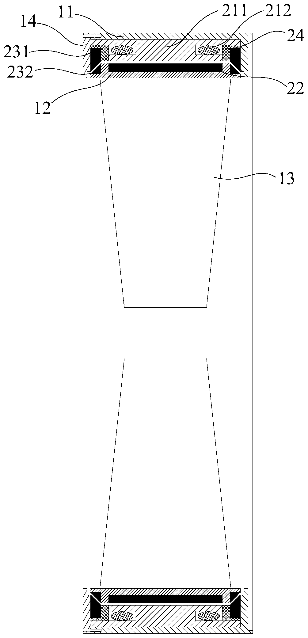
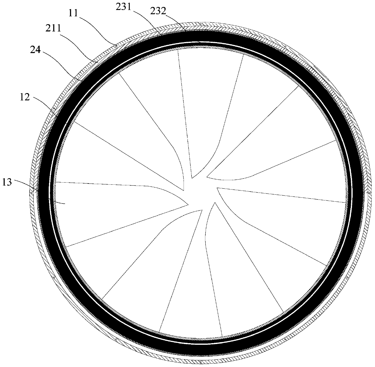
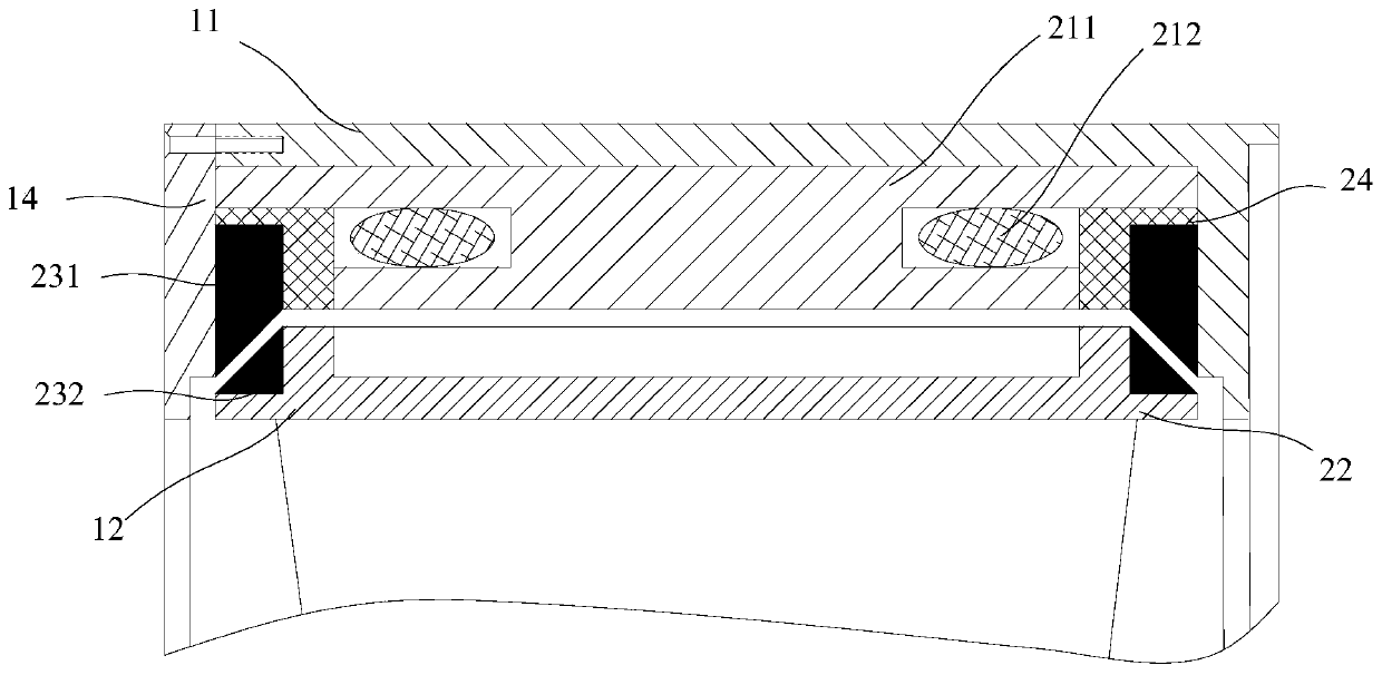
[0051] Refer below Figure 1 to Figure 8 Shaftless fans and air conditioners according to some embodiments of the present invention are described.

[0052] like figure 1 As shown, an embodiment of...


PUM


Abstract

The invention provides a shaftless fan and an air conditioner. The shaftless fan comprises an outer cylinder and an inner cylinder, wherein the inner wall of the outer cylinder is provided with a stator iron core and a winding coil wound on the stator iron core, the inner cylinder is arranged in the outer cylinder, the inner cylinder and the outer cylinder are coaxial, the outer peripheral surfaceof the inner cylinder is provided with first magnets corresponding to the stator iron core so that the inner cylinder can rotate relative to the outer cylinder, and a plurality of blades are arrangedon the inner peripheral surface of the inner cylinder. According to the technical scheme, the fan blade root reflux loss and the blade top clearance loss can be reduced, the ventilation efficiency iseffectively improved, meanwhile, the fan structure is simplified, and the noise is reduced.

Description

technical field [0001] The invention relates to the technical field of ventilation, in particular to a shaftless fan and an air conditioner. Background technique [0002] At present, in people's daily life, the fan has become a relatively common heat dissipation tool. In particular, in the process of using the air conditioner, it has become a common driving method to discharge the cold or hot air from the air conditioner through the fan to the room. In the prior art, the fans of the existing air conditioners all adopt a motor with a drive shaft and a structure with multiple blades at one end of the drive shaft. However, due to structural limitations, it is easy to cause backflow loss at the blade root and blade tip clearance loss, which affects ventilation efficiency. . Contents of the invention [0003] The present invention aims to solve at least one of the technical problems existing in the prior art or related art. [0004] Therefore, an object of the present inventi...

Claims


Application Information

Patent Timeline
IPC IPC(8): F04D23/00F04D25/08F04D29/40F04D29/66F04D29/00H02K7/14F24F1/0018F24F1/38
CPCF04D23/00F04D25/0693F04D25/08F04D29/403F04D29/663F04D29/002H02K7/14F24F1/0018F24F1/38
Inventor 易正清李金波马列
Owner GD MIDEA AIR-CONDITIONING EQUIP CO LTD
Learn More