
Demisting and cooling integrated heat exchange tubes, demisting and cooling integrated heat exchange device and application thereof

A technology of heat exchange tubes and shells, applied in the field of demisting devices, which can solve the problems of large space occupation, high investment, and large fan output, and achieve the effects of reducing relative humidity, reducing flue gas temperature, and promoting condensation and precipitation

Inactive Publication Date: 2019-08-30
SHANDONG UNIV
View PDF5 Cites 4 Cited by
  • Summary
  • Abstract
  • Description
  • Claims
  • Application Information

AI Technical Summary

Problems solved by technology

However, the inventor believes that the existing demist and dust removal equipment still need to be installed separately, and there are problems such as large space occupation, high initial investment in equipment, and large fan output.

Method used


Image

  • Demisting and cooling integrated heat exchange tubes, demisting and cooling integrated heat exchange device and application thereof
  • Demisting and cooling integrated heat exchange tubes, demisting and cooling integrated heat exchange device and application thereof
  • Demisting and cooling integrated heat exchange tubes, demisting and cooling integrated heat exchange device and application thereof

Examples


Embodiment 1

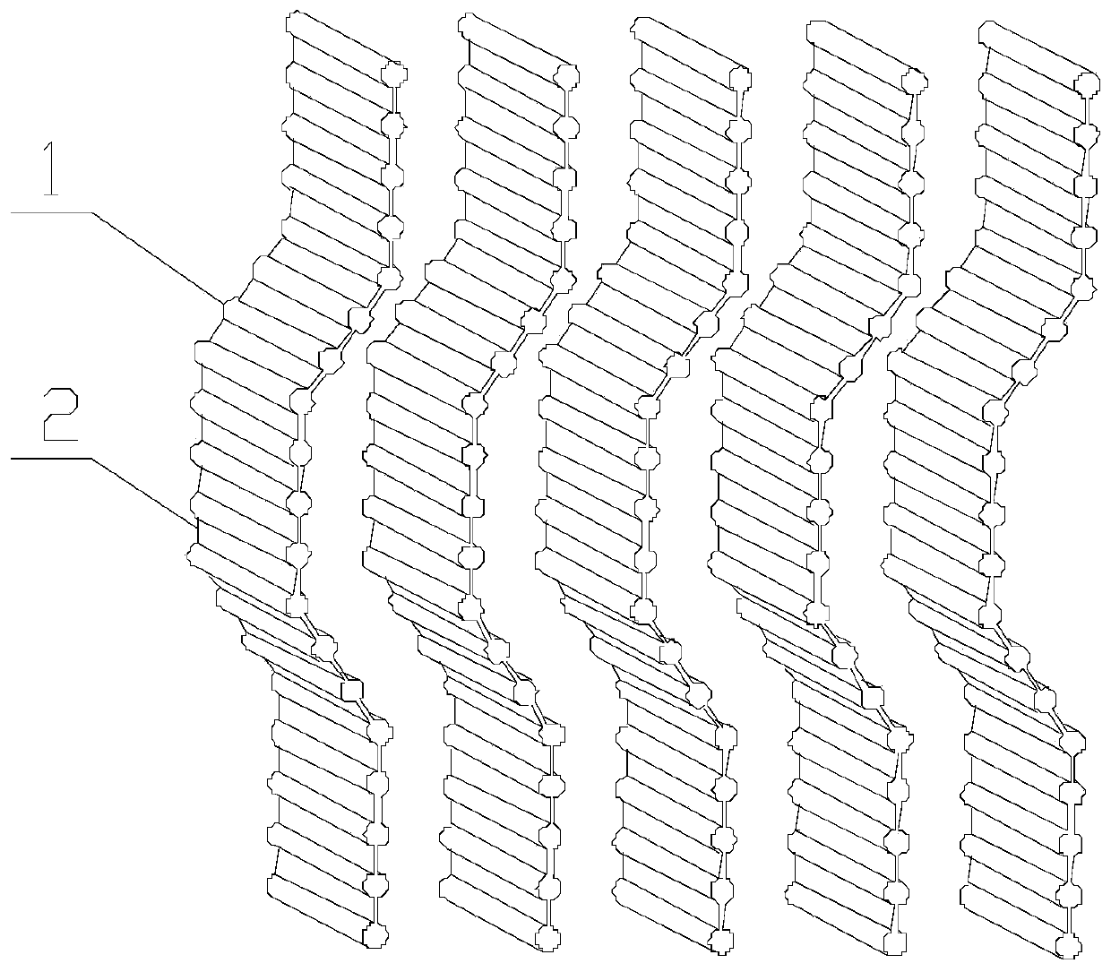
[0046] An integrated heat exchange tube for demisting and cooling, refer to figure 1 , which includes: heat exchange tubes 1 and connection plates 2, the heat exchange tubes 1 and connection plates 2 are distributed alternately, and the outer walls of the heat exchange tubes 1 and the outer surfaces of the connection plates are connected together to form a wave-shaped plate Structure; that is, every two adjacent heat exchange tubes are connected together by a connecting plate, and the nozzles of each heat exchange tube face the same direction.

Embodiment 2

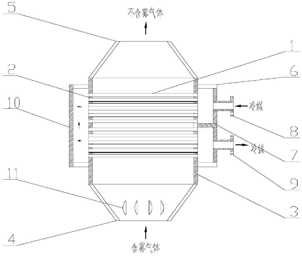
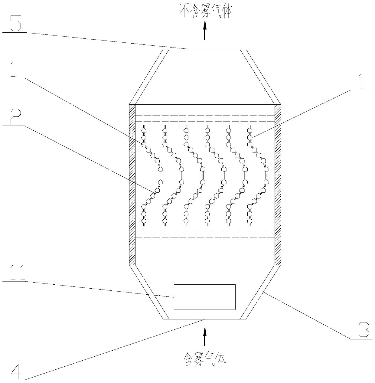
[0048] A vertical demisting and cooling integrated device, refer to figure 2 and 3 , which includes: the defogging and cooling integrated heat exchange tube in Example 1, a shell 3, a flue gas inlet 4, a flue gas outlet 5, a header 6, a header partition 7, a refrigerant inlet 8, and a refrigerant outlet 9 and coupler 10, where:

[0049] The housing 3 is arranged vertically, and the lower and upper ends of the housing 3 are the smoke inlet 4 and the smoke outlet 5 respectively. The tank partition 7 separates the header into upper and lower chambers; the refrigerant inlet 8 and the refrigerant outlet 9 are respectively arranged on the upper and lower chambers; the coupling 10 is arranged on the outer wall of the housing 3 and Located on the opposite side of the header 6; the integrated heat exchange tube for defogging and cooling is located in the housing 3, and the two ends of the heat exchange tube 1 are respectively connected with the header 6 and the coupler 10, that is, ...

Embodiment 3

[0051] A horizontal demisting and cooling integrated device, comprising: the demisting and cooling integrated heat exchange tube in Embodiment 1, a shell 3, a flue gas inlet 4, a flue gas outlet 5, a header 6, a header compartment Plate 7, refrigerant inlet 8, refrigerant outlet 9, coupling 10 and condensate outlet 12, where:

[0052] The housing 3 is arranged horizontally, and the left and right ends of the housing 3 are respectively the smoke inlet 4, the smoke outlet 5 or the smoke outlet 5, and the smoke inlet 4, and the lower wall of the housing 3 has a clip with respect to the horizontal plane. The condensed water outlet 12 is arranged on the lower wall of the casing 3 and is located on the lower side.

[0053] The header 6 is arranged on the outer wall of the housing 3, and the header 6 is provided with a header partition 7 to divide the header into upper and lower chambers; the refrigerant inlet 8 and the refrigerant outlet 9 are respectively arranged on the On the up...


PUM


Abstract

The invention belongs to the technical field of demisting devices and particularly relates to demisting and cooling integrated heat exchange tubes, a demisting and cooling integrated heat exchange device and application. The device comprises the demisting and cooling integrated heat exchange tubes, a shell, a flue gas inlet, a flue gas outlet, a header, a header partition plate, a refrigerant inlet, a refrigerant outlet and a coupler. The shell is arranged vertically, and the upper and lower ends of the shell are provided with the flue gas inlet and the flue gas outlet correspondingly. The header is arranged on the outer wall of the shell. The header partition plate is arranged in the header and partitions the header into an upper cavity and a lower cavity. The refrigerant inlet and the refrigerant outlet are formed in the upper cavity and the lower cavity correspondingly. The coupler is arranged on the outer wall of the shell and located on the opposite side of the header. The demisting and cooling integrated heat exchange tubes are located in the shell, and the two ends of the heat exchange tubes communicate with the header and the coupler correspondingly. According to the demisting and cooling integrated heat exchange tubes, the demisting and cooling integrated heat exchange device and application thereof, the heat exchange tubes are assembled in the form of baffle plates, accordingly, flue gas channels are formed, demisting and cooling of flue gas can be achieved at the same time, and the demisting and cooling integrated design is achieved.

Description

technical field [0001] The invention belongs to the technical field of defogging devices, and in particular relates to a defogging and cooling integrated heat exchange tube and its device and application. Background technique [0002] The information disclosed in the Background of the Invention is only intended to increase the understanding of the general background of the invention, and is not necessarily to be taken as an acknowledgment or any form of suggestion that the information constitutes the prior art that is already known to those skilled in the art. [0003] The demisting device is mainly used to remove the liquid droplets entrained in the gas phase medium in the gas-liquid separation tower, which can effectively reduce the loss of liquid medium, reduce the power consumption of the fan and weaken the corrosion of the device by the liquid medium, while effectively ensuring the efficiency of mass transfer. [0004] At present, wet desulfurization is the most mature ...

Claims


Application Information

Patent Timeline
Patent Type & Authority Applications(China)
IPC IPC(8): F28F1/22F28D7/08F28F19/00B01D53/26
CPCB01D53/265F28D7/08F28F1/22F28F19/00
Inventor 徐夕仁王晓哲崔琳陈莲芳周梦晨
Owner SHANDONG UNIV
Learn More