An array type heat exchange tube wall thickness on-line ultrasonic monitoring device
A technology for ultrasonic monitoring and heat exchange tubes, applied in measuring devices, using ultrasonic/sonic/infrasonic waves, instruments, etc., can solve the problems of unfavorable information management and maintenance, humid and hot environment, high labor intensity, etc., to achieve automatic online Long-term measurement, high measurement accuracy, flexible use effect
- Summary
- Abstract
- Description
- Claims
- Application Information
AI Technical Summary
Problems solved by technology
Method used
Image
Examples
specific Embodiment approach 1
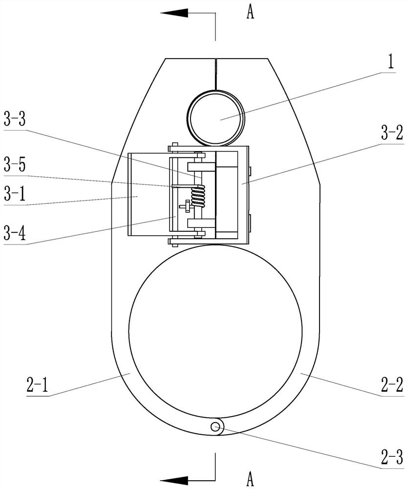
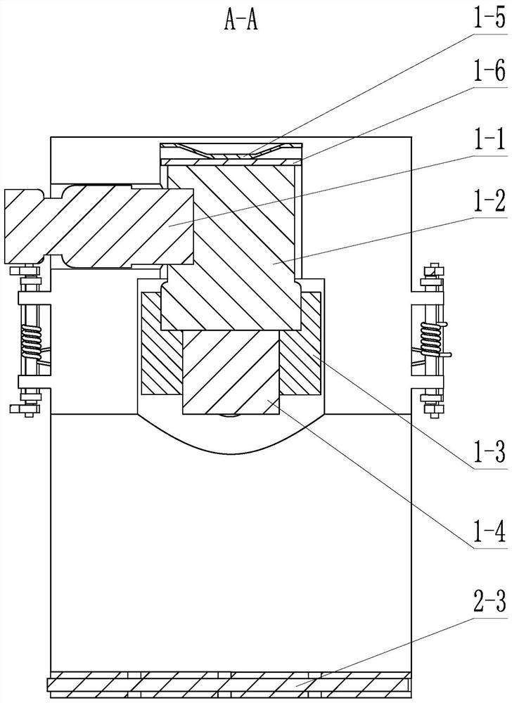
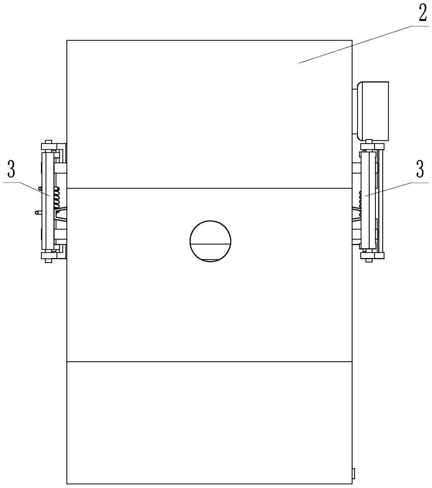
[0027] Specific implementation mode one: combine Figure 1 to Figure 15 and Figure 19 Describe this embodiment, an array type heat exchange tube wall thickness on-line ultrasonic monitoring device in this embodiment, the on-line ultrasonic monitoring device includes an ultrasonic thickness measuring device, a fastening positioning component and a couplant automatic circulation component, the ultrasonic thickness measuring device Including probe 1, probe 1 includes connecting pipeline 1-1, probe main body 1-2, ferrule 1-3 and probe delay block 1-4, connecting pipeline 1-1, probe main body 1-2, ferrule 1-3 Both the probe delay block 1-4 are of cylindrical structure, the probe main body 1-2 is vertically arranged, the outer circle of the upper part of the probe main body 1-2 is horizontally opened with a pipeline socket, and one end of the connecting pipeline 1-1 is inserted into the probe main body 1- 2, the probe delay block 1-4 is fixed on the lower end surface of the probe ...
specific Embodiment approach 2
[0032] Specific implementation mode two: combination Figure 7 , Figure 10 , Figure 12 and Figure 13 To illustrate this embodiment, the accommodating cavity 4 of this embodiment includes a first fitting groove 4-1 and a second fitting groove 4-2 arranged coaxially in the vertical direction, the first fitting groove 4-1 and the second fitting groove 4-2 The ferrule 1-3 is matched, the second assembly groove 4-2 is matched with the probe body 1-2, the first assembly groove 4-1 is located above the cylindrical through hole 2-4 and is connected with the cylindrical through hole 2-4 In communication, one side of the second assembly groove 4-2 offers a third assembly groove 4-3 along the horizontal direction, and one end of the third assembly groove 4-3 communicates with the second assembly groove 4-2, and the third assembly groove 4 -3 matches the connecting line 1-1. In this way, the third assembly groove 4-3 on the upper part is used for leading out the connecting pipeline...
specific Embodiment approach 3
[0033] Specific implementation mode three: combination figure 2 To illustrate this embodiment, the ultrasonic thickness measuring device of this embodiment also includes a reed 1-5 and a circular gasket 1-6. There are circular pads 1-6 and reeds 1-5. In this way, the fixing of the probe 1 in the vertical direction is realized by using the pressing device of the reed 1-5. The second assembly groove 4-2 on the top of the first separate entity 2-1 and the second separate entity 2-2 is used to provide the vertical direction pre-tightening force to the reed 1-5, and a thinner joint is connected below the reed 1-5. Circular spacers 1-6 with a thickness of 0.5 mm are used to prevent the direct contact area between the reeds 1-5 and the top of the probe from being too small, and the friction force is small to cause lateral displacement due to sliding. Other compositions and connections are the same as those in Embodiment 1 or Embodiment 2.
PUM
 Abstract
Description
Claims
Application Information
 - R&D
- Intellectual Property
- Life Sciences
- Materials
- Tech Scout
- Unparalleled Data Quality
- Higher Quality Content
- 60% Fewer Hallucinations
Browse by: Latest US Patents, China's latest patents, Technical Efficacy Thesaurus, Application Domain, Technology Topic, Popular Technical Reports.
© 2025 PatSnap. All rights reserved.Legal|Privacy policy|Modern Slavery Act Transparency Statement|Sitemap|About US| Contact US: help@patsnap.com


