Transmission-type photo-elastic instrument

A photoelasticity and transmission technology, applied in the field of photomechanics, can solve the problems of inconvenient research on small models, unsuitable for carrying and popularization, inconvenient to carry, etc., and achieves the effects of flexible and convenient carrying, material saving and simple structure

Pending Publication Date: 2019-08-30
TONGJI UNIV
View PDF1 Cites 2 Cited by
  • Summary
  • Abstract
  • Description
  • Claims
  • Application Information

AI Technical Summary

Problems solved by technology

[0003] The photoelasticity instrument currently used in classroom teaching has a complex structure, requires a specific light source, requires multiple precision optical parts, and is large in size and high in cost, so it cannot be popularized in large quantities
At present, there are very few miniaturized transmission photoelastic instruments, which are inconvenient to carry, and it is also inconvenient to study small models, and most of them are horizontal structures
[0004] Chinese invention patent CN105928775 specification discloses a microphotoelastic experimental system for material micro-region stress field testing, including: a loading unit, including a clamp module for fixing the sample material and for applying a quantitative load to the sample material The load controller; the optical unit includes a microscope, a microphotoelasticity instrument placed in the microscope observation area and adapted to the microscope workspace; the optical components include a polarizer that can be moved out or into the optical path, two 1 / 4 wave film and an analyzer; the loading unit can be a loading testing machine capable of micro-stretching; although it can realize the function of an optical elastic instrument, its structure is relatively complicated and its cost is high, so it is not suitable for portability and popularization

Method used


Image

  • Transmission-type photo-elastic instrument
  • Transmission-type photo-elastic instrument
  • Transmission-type photo-elastic instrument

Examples


Embodiment

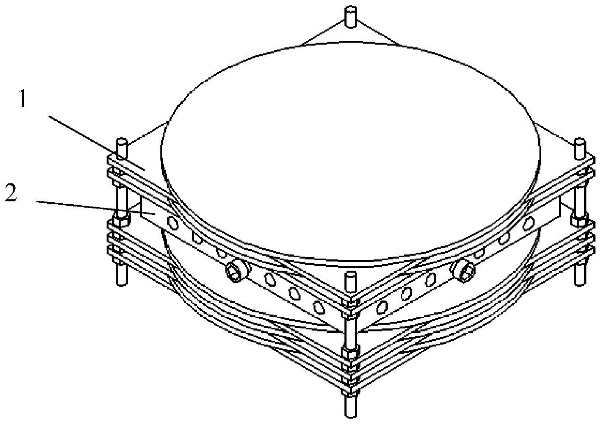
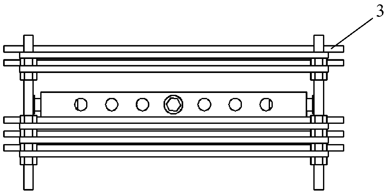
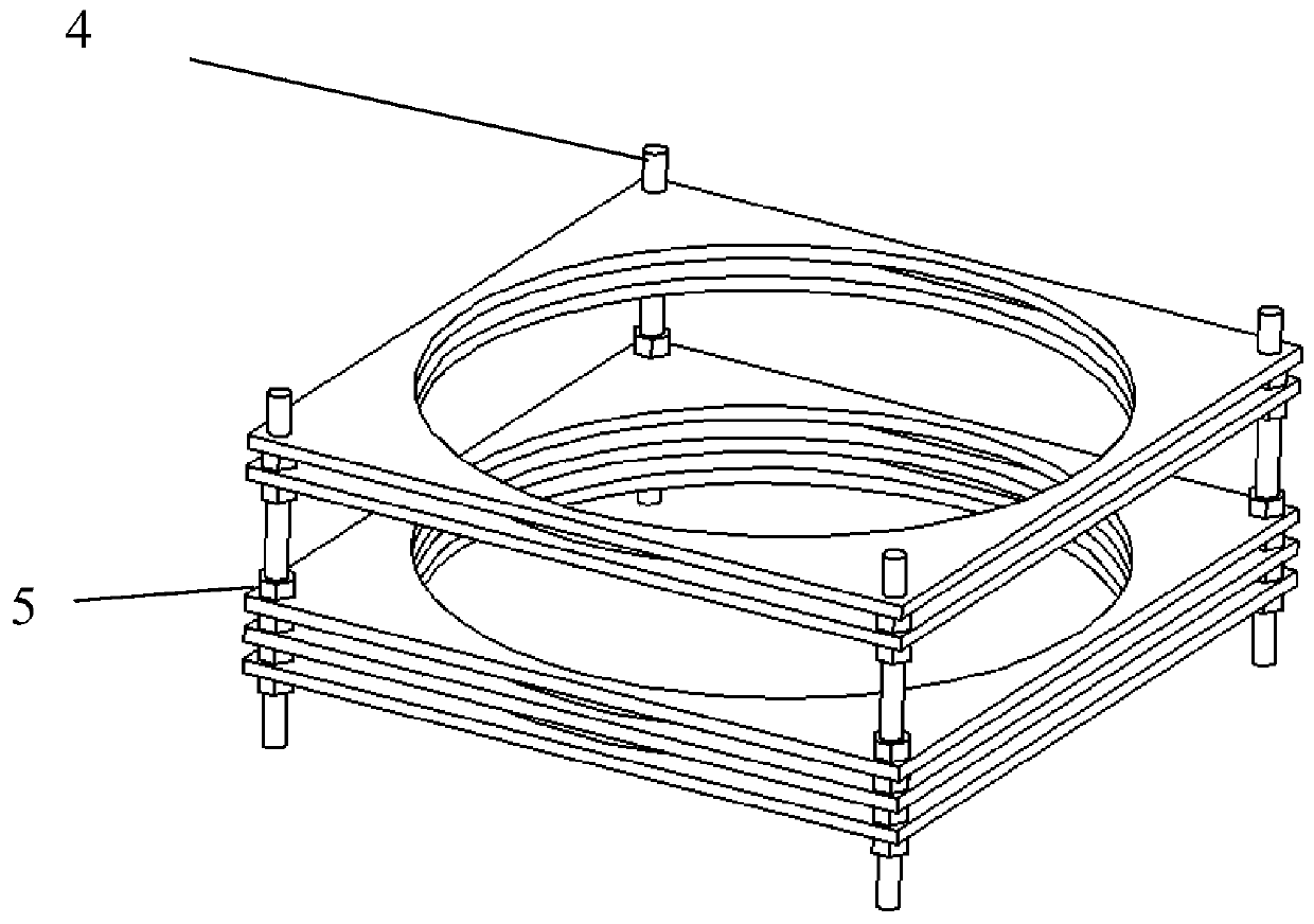
[0040] A transmission photoelasticity instrument, comprising a bracket 1, a rotating assembly and a fixing device 2, the rotating assembly is used to adjust the displayed interference fringe pattern, the fixing device 2 is used to fix a sample 8 and make the sample 8 generate stress, the bracket 1 includes A plurality of longitudinally spaced supporting plates, the rotating assembly includes a plurality of rotating bodies 3 that are consistent with the number of the supporting plates, and the plurality of rotating bodies 3 are connected to a plurality of longitudinally spaced supporting plates in one-to-one correspondence, and the fixing device 2 is connected to the plurality of supporting plates. One of the rotating body 3 is connected, and part of the rotating body 3 is provided with a 1 / 4 wave plate or a polarizing film.

[0041] A plurality of longitudinally spaced support plates and a plurality of rotating bodies 3 are transparent materials, and the plurality of longitudin...


PUM

PropertyMeasurementUnit
diameteraaaaaaaaaa

Abstract

The invention relates to a transmission-type photo-elastic instrument comprising a support (1) and a rotation assembly; the rotation assembly is rotationally arranged in the support and comprises a plurality of rotary bodies (3), a plurality of optical elements and a fixing device (2); the rotating bodies are laminated from top to bottom and are arranged at intervals; the plurality of optical elements are fixedly arranged on the rotating bodies (3); and the fixing device (2) is used for fixing a sample (8) and enabling the sample (8) to generate stress and is arranged in the middle of the rotation assembly. Compared with the prior art, the transmission-type photo-elastic instrument in the invention has the advantages of being simple in structure, convenient to use, small in size and convenient to carry, and the cost can be greatly reduced.

Description

technical field [0001] The invention relates to the technical field of photomechanics, in particular to a transmission photoelasticity instrument. Background technique [0002] The photoelasticity method, referred to as the photoelasticity method, is an experimental technique that combines optics and mechanics for stress analysis. It has a history of nearly 200 years. The development of industry in the 19th century, the production of optical instruments and transparent plastics enabled the application and development of this method and formed an independent discipline. Compared with other experimental stress analysis techniques such as strain electrical measurement, the photoelastic method has the following characteristics: 1) The photoelasticity experiment is a model experiment. When the photoelastic model and the real object (or prototype) meet a certain similarity relationship, whether it is a large structure such as a bridge, a dam, an aircraft, a ship, or a gas turbine...

Claims


Application Information

Patent Timeline
Patent Type & Authority Applications(China)
IPC IPC(8): G01L1/24
CPCG01L1/241
Inventor 郑红浩曾伟明鲁书浓朱金龙朱立明
Owner TONGJI UNIV
Why Eureka
Try Eureka