Semiconductor refrigeration chip aging test device

A technology of aging test and cooling chip, which is applied in the direction of semiconductor working life test and single semiconductor device testing, etc. It can solve the problems of low test accuracy and low efficiency of semiconductor cooling chip aging test, so as to prevent test failure and prevent test failure. Inefficiency, the effect of guaranteeing the test effect

Inactive Publication Date: 2019-08-30
泉州市依科达半导体致冷科技有限公司
View PDF0 Cites 1 Cited by
  • Summary
  • Abstract
  • Description
  • Claims
  • Application Information

AI Technical Summary

Problems solved by technology

[0004] The invention provides an aging test device for a semiconductor refrigerating plate, aiming at improving the technical problems of low efficiency and low testing accuracy of the existing semiconductor refrigerating plate aging test

Method used


Image

  • Semiconductor refrigeration chip aging test device
  • Semiconductor refrigeration chip aging test device
  • Semiconductor refrigeration chip aging test device

Examples


Embodiment 1

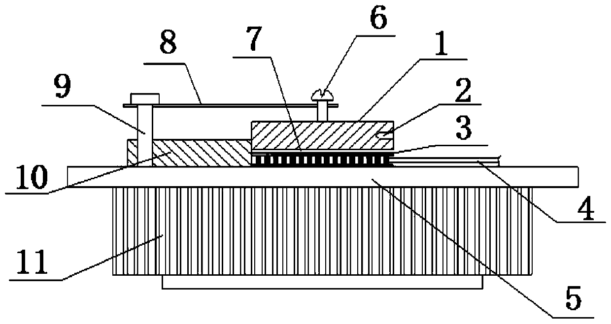
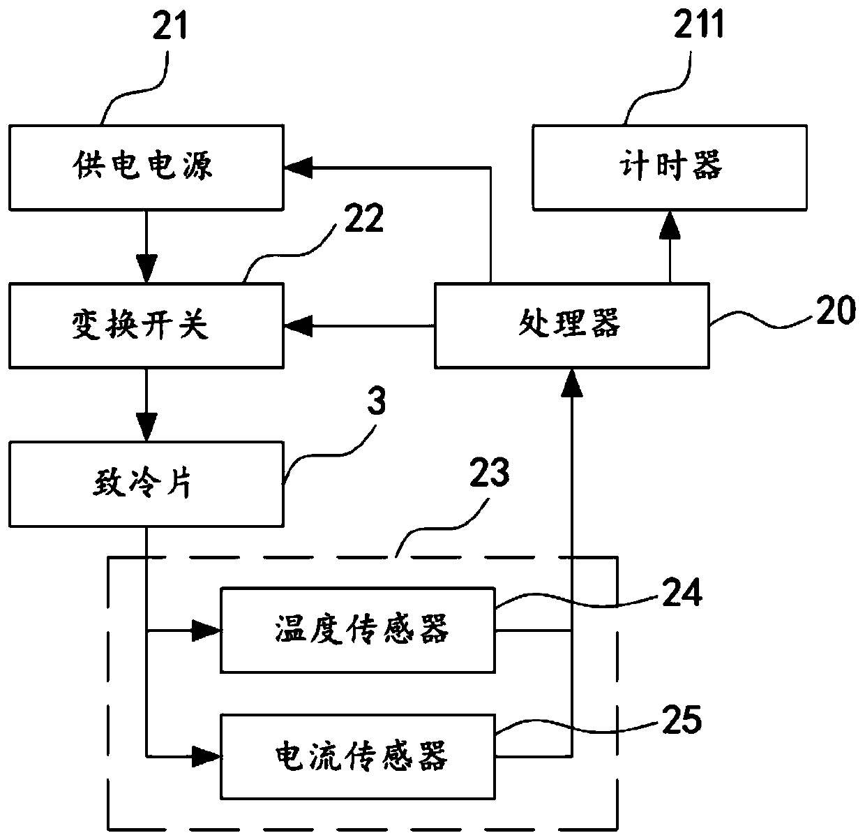
[0027] Example 1, see Figure 1 to Figure 2 , The first embodiment of the present invention provides a semiconductor refrigeration chip aging test device, including a test bench 5, a limit assembly arranged on the test bench 5, a first heat conduction plate 1 connected to the limit assembly, The second heat conduction plate 11 located at the bottom of the test bench 5 and the test controller electrically connected to the refrigerating plate 3 to be tested, the bottom surface of the first heat conducting plate 1 is attached to the top surface of the refrigerating plate 3 to be tested. Together, the test bench 5 is used to play the role of bearing and fixing the limit assembly, the first heat conduction plate 1, the second heat conduction plate 11 and the test controller, so as to improve the aging test of the semiconductor refrigeration plate. The stability of the overall structure of the device, the limit assembly is used to prevent the position of the refrigerating plate 3 to...

Embodiment 2

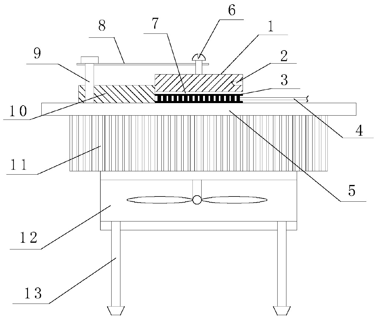
[0042] Embodiment 2, with reference to image 3 It is a schematic structural diagram of a semiconductor refrigeration chip aging test device provided by the second embodiment of the present invention. The structure of the second embodiment is roughly the same as that of the first embodiment. The difference is that in this embodiment, the second heat conducting plate 11 is provided with a ventilation cooling seat 12 on the side facing away from the test bench 5, and a cooling fan is arranged inside the ventilation cooling seating 12, and the cooling fan is used to improve the heat conduction efficiency of the second heat conducting plate 11. The bottom of the ventilation heat dissipation seat 12 is provided with a plurality of support feet 13, and the end of the support feet 13 is provided with a rubber pad, and the rubber pad is used to improve the friction between the support feet 13 and the ground, thereby effectively preventing the The movement of the positions of the suppo...


PUM


Abstract

The invention provides a semiconductor refrigeration chip aging test device, and relates to the technical field of semiconductor refrigeration chips. The semiconductor refrigeration chip aging test device comprises a test bench, a limiting component, a first heat conduction plate, a second heat conduction plate and a test controller, a bottom surface of the first heat conduction plate is laminatedwith a cold surface of a refrigeration chip to be tested, the test controller comprises a processor, a power supply, an alteration switch, a detection component and a timing counter, the alteration switch is arranged between the power supply and the refrigeration chip to be tested, the detection component comprises a temperature sensor and a current sensor, and an input end of the current sensoris electrically connected with the refrigeration chip. According to the semiconductor refrigeration chip aging test device provided by the invention, by means of the design of the test controller, anaging test is performed on the refrigeration chip to be tested in an automatic manner to prevent the phenomena of low test efficiency and low test accuracy due to manual test.

Description

technical field [0001] The invention relates to the technical field of semiconductor refrigerating sheets, in particular to an aging test device for semiconductor refrigerating sheets. Background technique [0002] The semiconductor refrigerating plate is composed of a porcelain plate and a plurality of crystal grains welded on the porcelain plate. In the middle of the refrigerating plate are crystal grains arranged equidistantly, and the two sides are porcelain plates. The working operation of the semiconductor refrigerator uses a DC power supply, which can be cooled and heated, and the cooling or heating can be realized on the same refrigerator by changing the polarity of the DC voltage. The semiconductor refrigerator is made of the Peltier effect of semiconductor materials. The so-called Peltier effect refers to the phenomenon that when a direct current passes through a galvanic couple composed of two semiconductor materials, one end absorbs heat and the other end release...

Claims


Application Information

Patent Timeline
Patent Type & Authority Applications(China)
IPC IPC(8): G01R31/26
CPCG01R31/2642
Inventor 阮秀沧黄锦局
Owner 泉州市依科达半导体致冷科技有限公司
Why Eureka
Try Eureka