Supercharge Your Innovation With Domain-Expert AI Agents!

Isolation amplifier device

An isolation amplifier, high isolation technology, used in transformers, inductors, transformer/inductor components, etc., can solve the problem of poor anti-radiation interference ability, difficult miniaturization of products, and poor influence of output signal zero point and gain accuracy. big problem

Pending Publication Date: 2019-08-30
镇江英创电力电子有限公司
View PDF0 Cites 0 Cited by
  • Summary
  • Abstract
  • Description
  • Claims
  • Application Information

AI Technical Summary

Problems solved by technology

[0005] 1. For example, the PWM modulation circuit uses a triangular wave to compare with the input signal to achieve modulation. The linearity of the edge of the triangular wave generated by the oscillator and formed by charging and discharging the capacitor directly affects the accuracy of the measurement, and its linearity is greatly affected by components. Obviously, it has a great influence on the zero point and gain accuracy of the output signal of the product
[0006] 2. The high-isolation transformer and high-isolation power transformer used in the existing high-isolation amplifier, the internal coil is designed to be wound on the magnetic core by enameled wire, and it is difficult to make each group of coils under high isolation voltage. To complete shielding, this leads to poor anti-radiation interference ability of the product in harsh electromagnetic environments, and the high isolation transformer and high isolation power transformer are large in size, and it is difficult to miniaturize the product
For the demodulation circuit, this is a floating signal, and its level must be precisely fixed. If it is not handled properly, it will affect the zero point and dynamic range of the signal.

Method used


Image

  • Isolation amplifier device
  • Isolation amplifier device
  • Isolation amplifier device

Examples


Embodiment 1

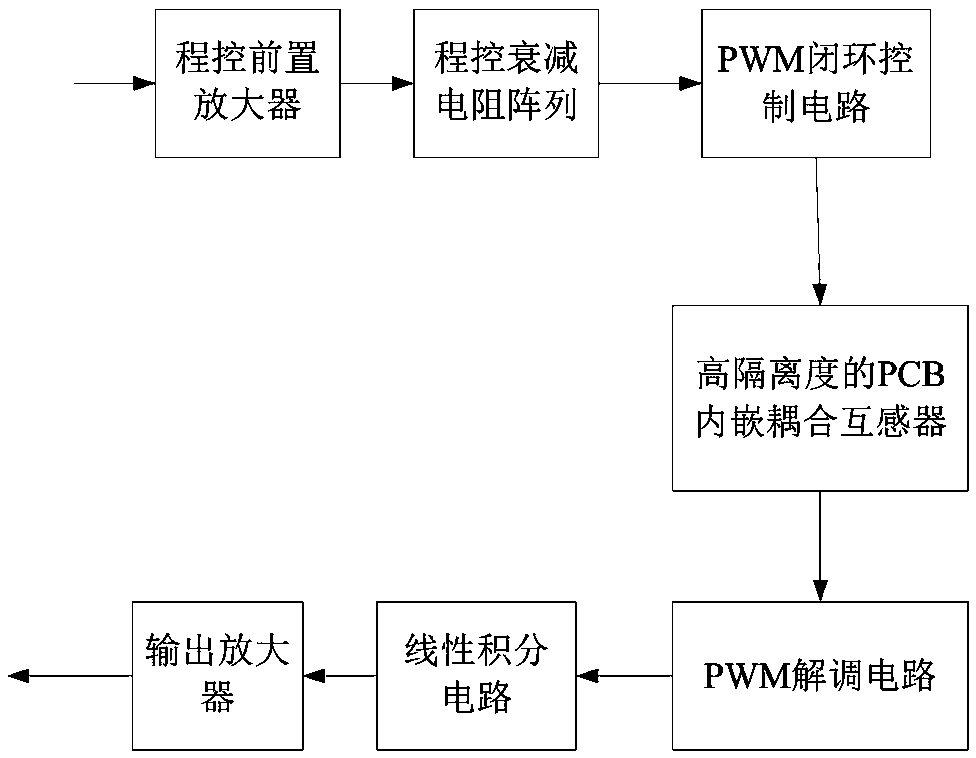
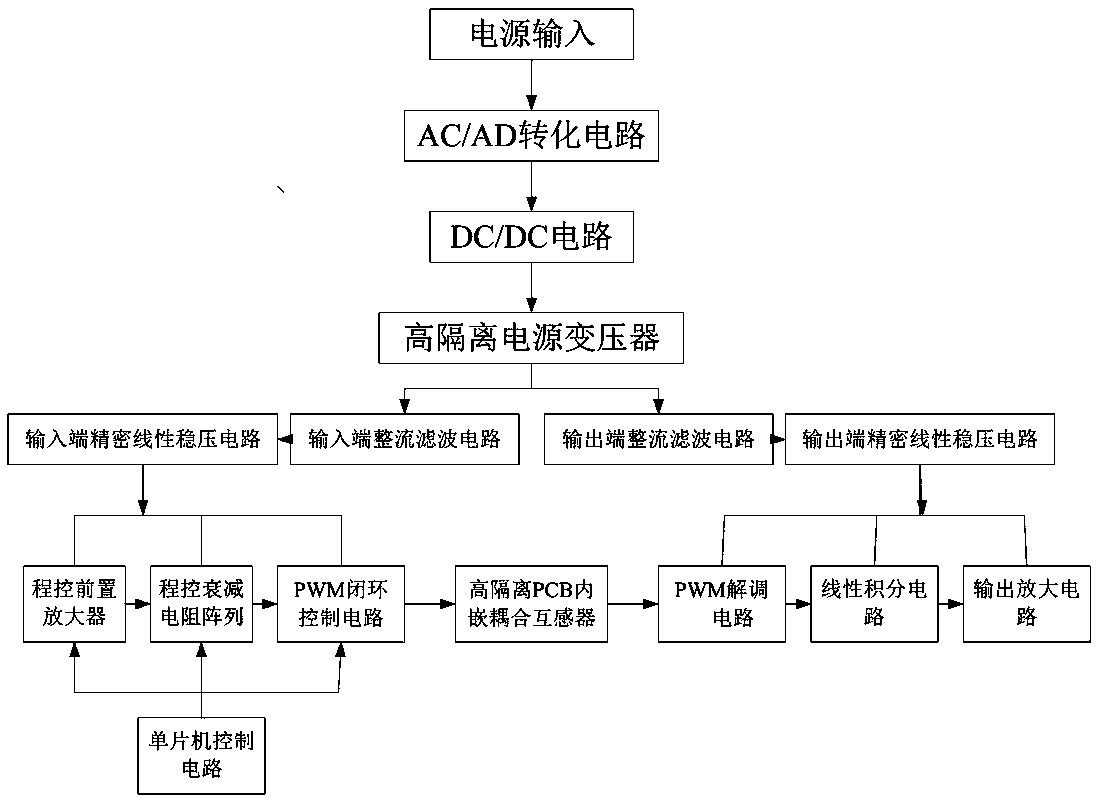
[0048] Example 1, as figure 1 , 2 , 3, in the isolation amplifier in this embodiment, the signal to be tested passes through the program-controlled preamplifier, program-controlled attenuation resistor array, PWM closed-loop control circuit, high-isolation PCB embedded coupling transformer, PWM demodulation circuit, linear Integrator circuit, output amplifier. The PWM closed-loop control circuit and the high-isolation PCB embedded coupling transformer are controlled by the single-chip microcomputer control circuit.

[0049] The power supply of the device of this embodiment consists of an AC / DC conversion circuit, a PWM control circuit, a high isolation power transformer, an input end rectification filter circuit, an input end precision linear voltage stabilization circuit, an output end rectification filter circuit, and an output end precision linear voltage stabilization circuit. Circuit composition.

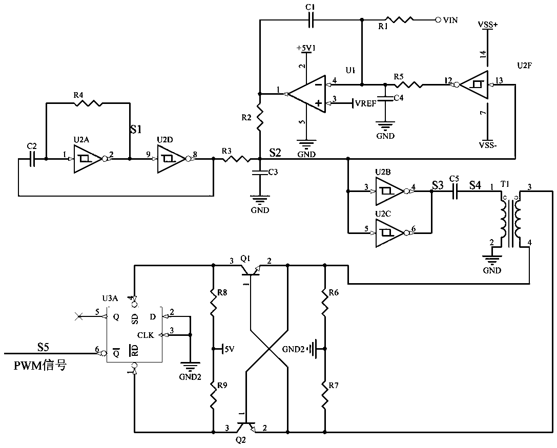
[0050] PWM closed-loop control circuit such as figure 2 As shown, it ...


PUM


Abstract

The invention discloses an isolation amplifier device which comprises a conditioning circuit, an amplification output circuit and an electromagnetic isolation circuit, wherein the conditioning circuitand the amplification output circuit condition an input signal to be tested; the electromagnetic isolation circuit is arranged between the conditioning circuit and the amplification output circuit; the electromagnetic isolation circuit comprises a PWM closed-loop control circuit, a high-isolation PCB embedded coupling transformer and a PWM demodulation circuit. An input signal to be tested is conditioned by the conditioning circuit and then is output to be connected with the PWM closed-loop control circuit; a PWM modulation signal is output after modulation of the PWM closed-loop control circuit and is connected with a primary coil of the high-isolation PCM embedded coupling transformer, a secondary coil of the high-isolation PCB embedded coupling transformer is connected with the PWM demodulation circuit, and the PWM demodulation circuit carries out demodulation output, and is connected with a wiring integration circuit and a amplification output circuit. The invention provides a high-isolation multi-range precision program-controlled amplifier device capable of realizing high isolation by using conventional components. The device occupies a very small PCB area, and is very easyto miniaturize, high in anti-interference capability and good in electromagnetic compatibility.

Description

technical field [0001] The invention relates to an isolation amplifier, in particular to a high-isolation multi-range precision program-controlled amplifier device in the field of power electronic measurement, which is an isolation amplifier device based on electromagnetic isolation PWM technology. Background technique [0002] With the development of science and technology, higher working voltage is used in high-power equipment such as rail transit, industrial control, power grid, and new energy. The monitoring of these high-voltage systems is mainly to ensure the safety of people and equipment. In these high-power devices, there are high common-mode voltage signals. To monitor these signals, high-isolation, high-reliability, and high-precision monitoring equipment must be used. [0003] At present, in the monitoring circuit, the signal to be tested in the high-voltage system is conditioned, and after the conditioned signal is isolated, the output is amplified, and finally ...

Claims


Application Information

Patent Timeline
IPC IPC(8): H03K7/08H01F27/28H01F27/36H01F38/20
CPCH03K7/08H01F27/2804H01F27/288H01F27/36H01F38/20H01F2027/2809
Inventor 管怀军吕华平吴圣帆
Owner 镇江英创电力电子有限公司
Features
  • R&D
  • Intellectual Property
  • Life Sciences
  • Materials
  • Tech Scout
  • Unparalleled Data Quality
  • Higher Quality Content
  • 60% Fewer Hallucinations
Learn More