Three motor driven single-screw compressor control method
A single-screw compressor and control method technology, applied in machine/engine, pump control, mechanical equipment, etc., can solve problems such as poor effect, no large-scale promotion to the market, etc., and achieve the effect of stepless variable flow regulation and control Reliable, easy-to-control results
- Summary
- Abstract
- Description
- Claims
- Application Information
AI Technical Summary
Problems solved by technology
Method used
Image

Examples
Embodiment 1
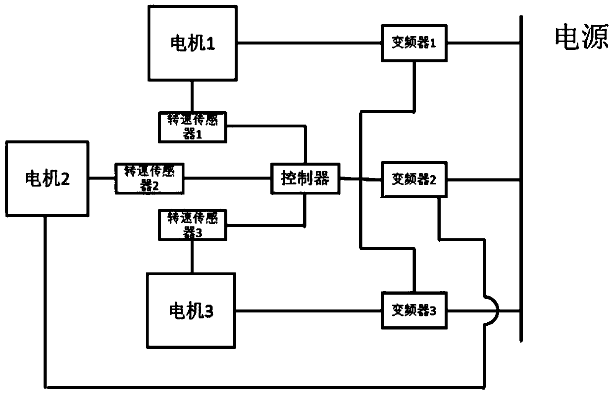
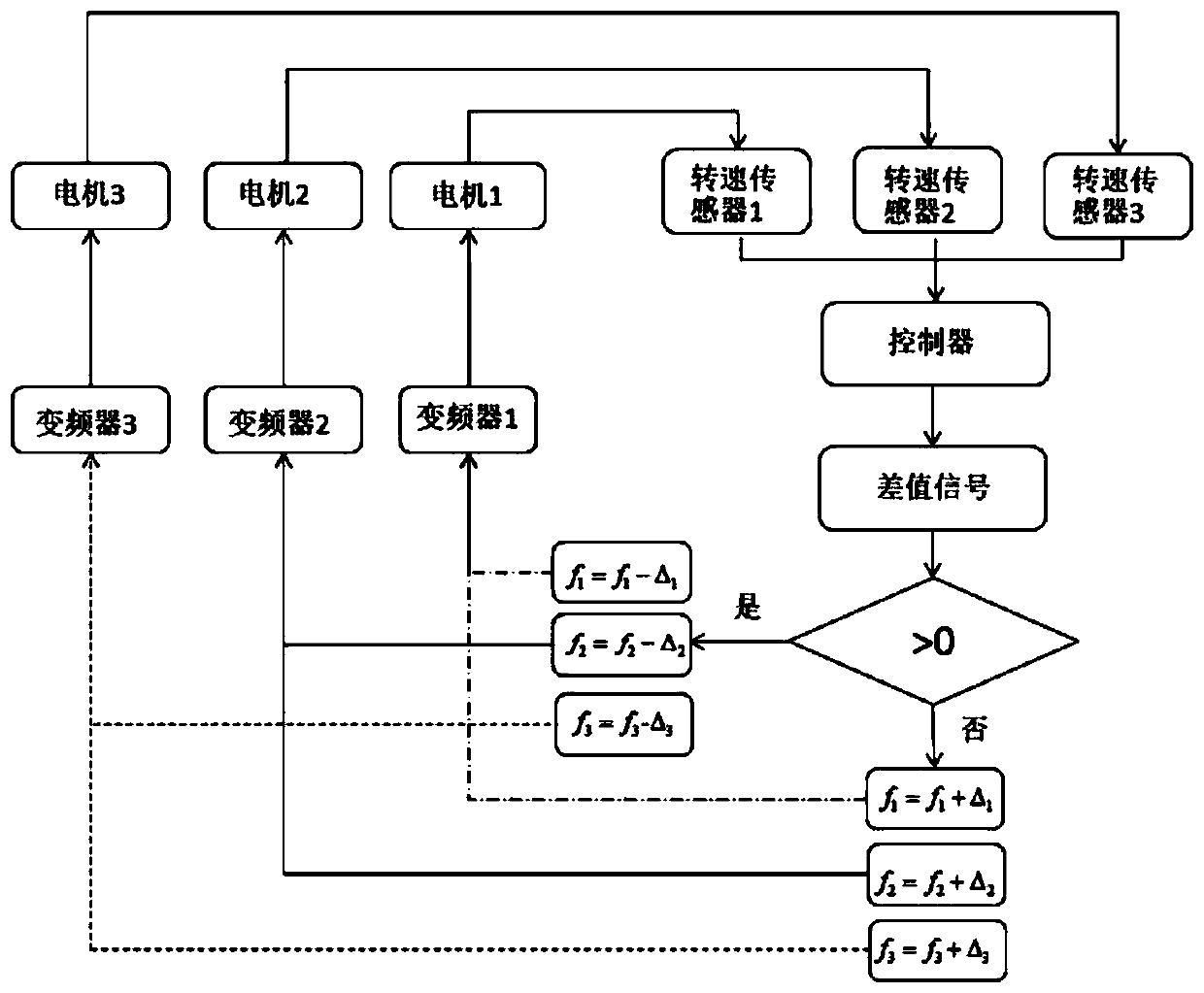
[0038] see Figure 3-4 , each of the three motors is equipped with a speed sensor, the motors connected to the two star wheels are respectively numbered as the first motor and the third motor, and the motor connected to the screw is the second motor, and the numbers of the speed sensor, the controller and the frequency converter are the same; The speed signals of the first speed sensor and the third speed sensor are analyzed by the first controller, the speed is set in the first controller, and the difference between the speed signals of the first motor and the third motor is analyzed according to the first controller, and according to the difference The signal controls the frequency of the first frequency converter and the third frequency converter to increase or decrease, thereby controlling the speed of the first motor and the third motor; the speed signal of the second speed sensor is analyzed by the second controller, and the second controller and the first The controller...
Embodiment 2
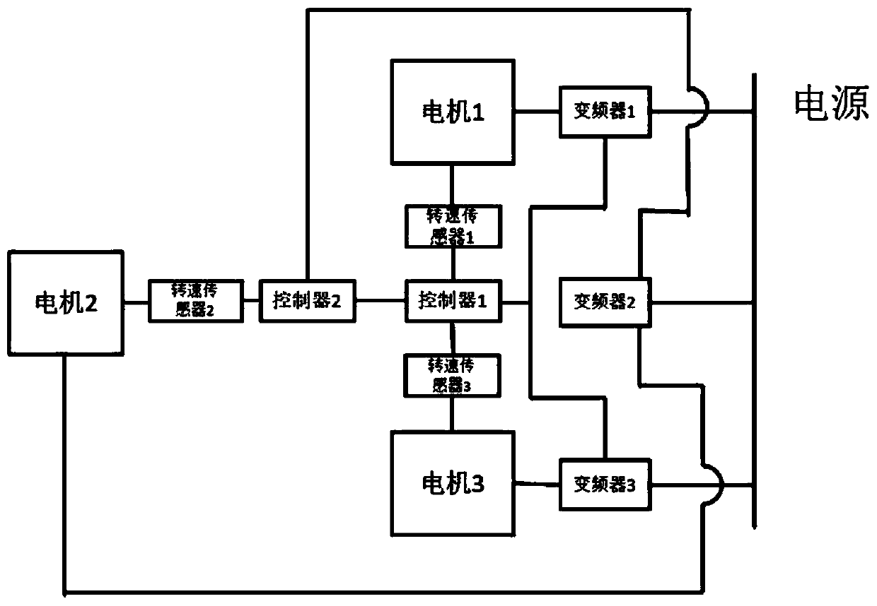
[0040] join Figure 5-6 , install a speed sensor for each of the three motors, the motors connected to the two star wheels are respectively numbered as the first motor and the third motor, and the motor connected to the screw is the second motor, and the numbers of the speed sensor, the controller and the frequency converter are the same; First, set the rotational speed in the second controller, control the frequency of the second inverter, and make the second motor run at the set rotational speed, and the rotational speed signals of the first rotational speed sensor and the second rotational speed sensor are analyzed by the first controller. Get the difference between the speed signals of the first motor and the second motor, and control the frequency increase or decrease of the first frequency converter according to the difference signal, and then control the speed of the first motor; in the same way, the third speed sensor The speed signal from the second speed sensor is an...
Embodiment 3
[0042] see Figure 7-8 , each of the three motors is equipped with a speed sensor, the motors connected to the two star wheels are respectively numbered as the first motor and the third motor, and the motor connected to the screw is the second motor, and the numbers of the speed sensor, the controller and the frequency converter are the same; set The fourth controller analyzes the speed signals of the three speed sensors through the fourth controller, sets the speed in the fourth controller, and feeds back the speed signals of the three motors through the first controller and the fourth controller. The controller analyzes the difference between the speed signals of the first controller and the fourth controller, controls the frequency of the first frequency converter to increase or decrease according to the difference signal, and then controls the speed of the first motor; through the second controller and the fourth controller The controller analyzes the difference between th...
PUM
 Abstract
Description
Claims
Application Information
 - R&D
- Intellectual Property
- Life Sciences
- Materials
- Tech Scout
- Unparalleled Data Quality
- Higher Quality Content
- 60% Fewer Hallucinations
Browse by: Latest US Patents, China's latest patents, Technical Efficacy Thesaurus, Application Domain, Technology Topic, Popular Technical Reports.
© 2025 PatSnap. All rights reserved.Legal|Privacy policy|Modern Slavery Act Transparency Statement|Sitemap|About US| Contact US: help@patsnap.com