Method and system for long-distance conveying of condensate polishing resin
A technology of condensate fine treatment and long-distance transportation, which is applied in the direction of ion exchange column/bed method, conveyor, conveying bulk materials, etc., can solve the problems of resin wear and pipe blockage, and achieve the purpose of alleviating blockage and resin wear and high conveying rate effect
- Summary
- Abstract
- Description
- Claims
- Application Information
AI Technical Summary
Problems solved by technology
Method used
Image

Examples
Embodiment 1
[0023] The method for long-distance transportation of condensate polishing resin of the present invention comprises the following steps:
[0024] The resin to be transported is first conveyed by hydraulic conveying, then conveyed by pneumatic conveying, and then conveyed by mixing hydraulic and pneumatic.
Embodiment 2
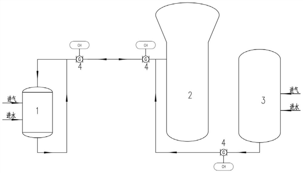
[0026] The system for long-distance delivery of condensate finishing resin in the present invention includes a resin delivery pipeline, a flushing water device and a compressed air system, wherein the outlet of the flushing water device, the outlet of the compressed air system and the inlet of the resin delivery pipeline are all connected to the resin The source node is connected, the outlet of the delivery pipeline is connected with the resin destination node, the resin delivery pipeline is provided with a pipeline sight glass monitoring device 4, the outlet of the flushing water device is provided with a first valve, and the outlet of the compressed air system is provided with a second valve. Two valves, the outer wall of the resin conveying pipeline is provided with antifreeze equipment.
[0027] When working, first open the first valve and close the second valve, use the flushing water output by the flushing water device as power to transport the resin in the resin source n...
Embodiment 3
[0029] refer to figure 1 , there are two resin transmissions in this embodiment, the first time: when the resin in the high-speed mixed bed 1 fails, the high-speed mixed bed 1 is used as the resin source node, and the high-tower separation tower 2 is used as the resin destination node to carry out the resin The second time: when the resin is regenerated and mixed, the resin mixing tank 3 is used as the resin source node, and the high-speed mixed bed 1 is used as the resin destination node for resin delivery.
[0030] In addition, during the conveying process, the resin conveying situation is observed through the pipe sight mirror monitoring device 4 .
[0031] The invention is applicable to the case where the regeneration equipment and the ion exchanger share a set of acid-base metering system for condensate polishing treatment resin and boiler supply water resin regeneration in a power plant, and can be used for active units and newly-built units.
[0032] The invention solv...
PUM
 Abstract
Description
Claims
Application Information
 - R&D
- Intellectual Property
- Life Sciences
- Materials
- Tech Scout
- Unparalleled Data Quality
- Higher Quality Content
- 60% Fewer Hallucinations
Browse by: Latest US Patents, China's latest patents, Technical Efficacy Thesaurus, Application Domain, Technology Topic, Popular Technical Reports.
© 2025 PatSnap. All rights reserved.Legal|Privacy policy|Modern Slavery Act Transparency Statement|Sitemap|About US| Contact US: help@patsnap.com