Degassing disc for gas turbine lubricant box

A technology for lubricating oil tanks and gas turbines, which is applied in the direction of engine lubrication, turbine/propulsion device lubrication, and lubricating parts. It can solve the problems of reducing the gas content of lubricating oil, high manufacturing costs, and complex structures, and achieves reductions in impact potential energy, Effect of reduced air, large free surface area

Active Publication Date: 2019-09-03
HANGZHOU TURBINE POWER GRP
View PDF9 Cites 0 Cited by
  • Summary
  • Abstract
  • Description
  • Claims
  • Application Information

AI Technical Summary

Problems solved by technology

Although this technology can reduce the gas content in lubricating oil to a certain extent, it is not suitable for large-scale production due to its complex structure and high manufacturing cost.
[0004] Other oil return devices used in the prior art usually directly discharge into the oil tank through the oil return pipe, or the oil return pipe is set to have a certain slope for buffering, but this method can only reduce the oil return discharge to a certain extent. When entering the oil tank, it impacts the air mixed in, but it cannot remove the gas that has been entrained in the returned oil.

Method used


Image

  • Degassing disc for gas turbine lubricant box
  • Degassing disc for gas turbine lubricant box
  • Degassing disc for gas turbine lubricant box

Examples


Embodiment 1

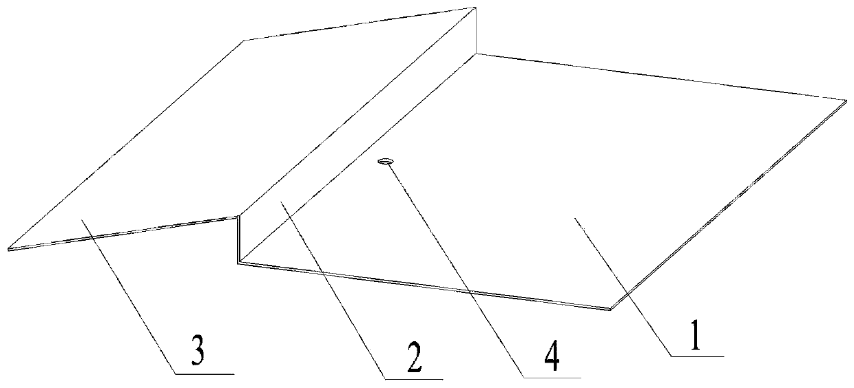
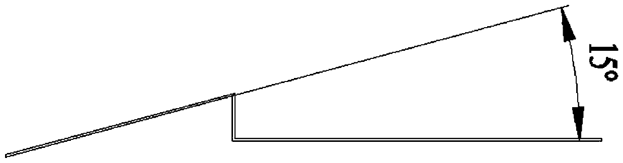
[0036] The degassing tray provided in this embodiment includes: the degassing tray body, which is horizontally arranged on the inner wall of the fuel tank and is lower than the oil return port of the system, and is used to accept the oil return of the system; One side of the mouth, the bottom of the step is connected to the body of the degassing plate; the slope, the top of the slope is connected to the top of the step, and the end of the slope goes deep into the interior of the fuel tank; the oil drain hole is opened on the body of the degassing plate, and the diameter of the oil drain hole is 25mm. When this embodiment is actually used in a certain gas turbine lubricating oil tank, the amount of lubricating oil required by the gas turbine is 1800L / min, and the total volume of the lubricating oil tank is 13.7m 3 , the oil storage area of ​​the fuel tank is 15m 2 , the actual height inside the fuel tank is 0.91m. There are two degassing discs in the fuel tank. The flow rate ...


PUM


Abstract

The invention provides a degassing disc for a gas turbine lubricant box, belongs to the field of power device oil supply, and particularly relates to the degassing disc for the gas turbine lubricant box. The degassing disc comprises a degassing disc body, a step, a slope and an oil drain hole. The degassing disc body is horizontally arranged at the position, lower than a system oil return port, ofthe inner wall of an oil tank and used for bearing system return oil. The step is vertically arranged on the side, away from the oil return port, of the degassing disc body, and the bottom of the step is connected with the degassing disc body. The top end of the slope is connected with the top of the step, and the tail end of the slope penetrates into the oil tank. The oil drain hole is formed inthe degassing disc body, impact potential energy generated when the return oil falls into the oil tank can be obviously reduced, and air mixed into lubricant can be reduced. In addition, the step isdesigned on the degassing disc, a certain oil reserve space is obtained, the situation that air of the lubricant is fully exhausted before the lubricant circulates again can be guaranteed, and the occupied area and the manufacturing cost of the oil tank are effectively reduced.

Description

technical field [0001] The invention relates to the field of power plant oil supply, in particular to a degassing pan used for a lubricating oil tank of a gas turbine. Background technique [0002] The lubricating oil system is one of the important auxiliary systems in the gas turbine system, which provides clean and clean lubricating and cooling oil for the bearings of gas turbines, gearboxes, generators and other equipment to ensure the normal start-stop and safe operation of the gas turbine system . Lubricating oil will be mixed with a large number of air bubbles during operation, which will significantly increase the resistance of the oil pipeline, reduce the specific heat and heat transfer coefficient of the lubricating oil, not only reduce the heat transfer performance of the lubricating oil cooler, but also deteriorate the friction of the mating surface cooling and lubrication conditions. Therefore, in order to ensure that the lubricating oil has enough time to sepa...

Claims


Application Information

Patent Timeline
Patent Type & Authority Applications(China)
IPC IPC(8): F16N39/00F02C7/06
CPCF02C7/06F16N39/002
Inventor 何成俞胤杰陈泓波张春梅白东方马思亮隋永枫邵艳红李冬青吕荣阳杨晶晶
Owner HANGZHOU TURBINE POWER GRP
Why Eureka
Try Eureka