
Three-dimensional infrared radiation heating system

An infrared radiation, three-dimensional technology, applied in the field of three-dimensional infrared radiation heating system, can solve the problems of uneven temperature, reduce indoor air heating effect, increase infrared radiation reflectivity, etc., to achieve enhanced heating effect and stable structure The effect of improving the performance and uniformity of infrared radiation

Inactive Publication Date: 2019-09-03
ZHEJIANG LAISIAO ELECTRIC
View PDF10 Cites 3 Cited by
  • Summary
  • Abstract
  • Description
  • Claims
  • Application Information

AI Technical Summary

Problems solved by technology

[0007] 1. It is only installed on the ceiling and heated from top to bottom, so that the temperature in the air is uneven up and down, which will make people feel uncomfortable;
[0008] 2. The integrated ceiling is made of metal materials, which increases the reflectivity of infrared radiation, thereby reducing the heating effect on indoor air;

Method used


Image

  • Three-dimensional infrared radiation heating system
  • Three-dimensional infrared radiation heating system
  • Three-dimensional infrared radiation heating system

Examples


Embodiment 1

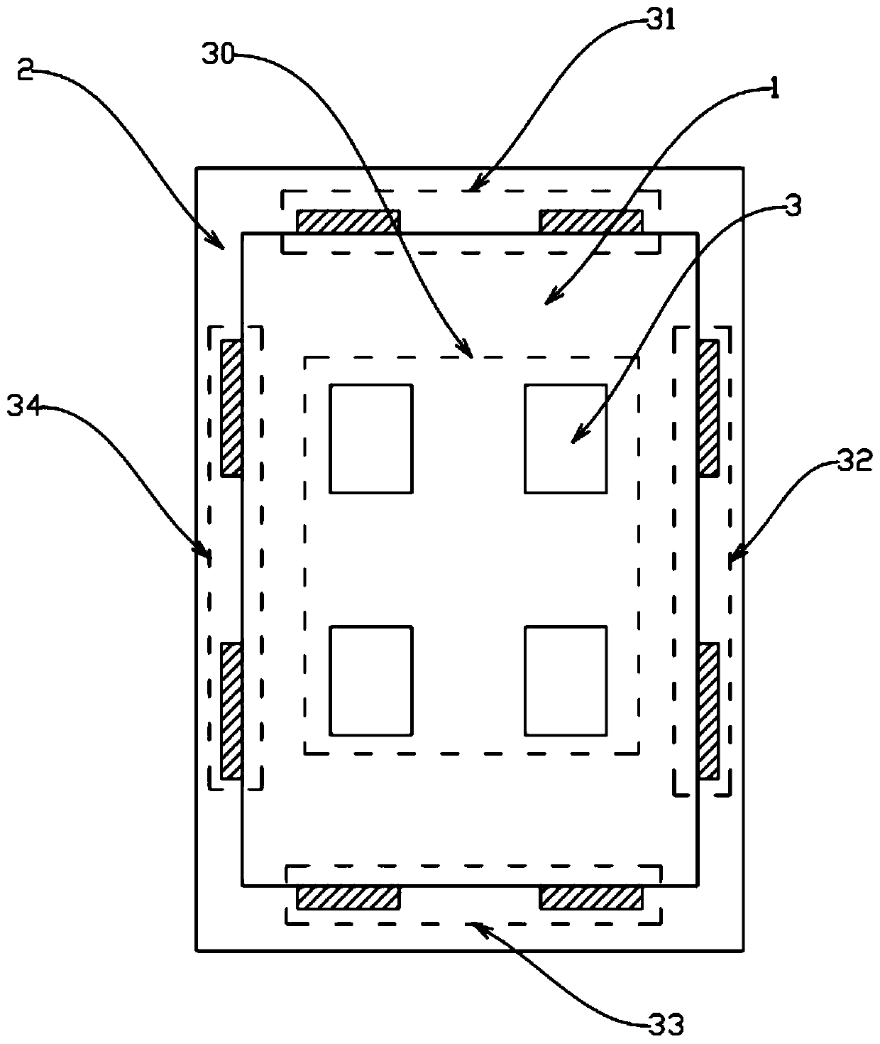
[0048] Such as Figure 1 to 3 As shown, a three-dimensional infrared radiation heating system includes a plurality of ceiling module units 3 arranged on a ceiling 1 and a wall 2 respectively, and the ceiling 1 is equipped with a first combination of multiple ceiling module units 3 The heating module 30, the proportion of the area S1 of the first heating module 30 on the ceiling 1> 50%; a second heating module 31, a third heating module 32, a fourth heating module 33, and a fifth heating module 34 formed by a combination of multiple ceiling module units 3 are respectively installed on the wall 2 adjacent to the ceiling 1, the The second heating module 31, the third heating module 32, the fourth heating module 33, and the fifth heating module 34 occupy an area S2> corresponding to the wall 2 30%; the first heating module 30, the second heating module 31, the third heating module 32, the fourth heating module 33, and the fifth heating module 34 are all connected to the controller 5...

Embodiment 2

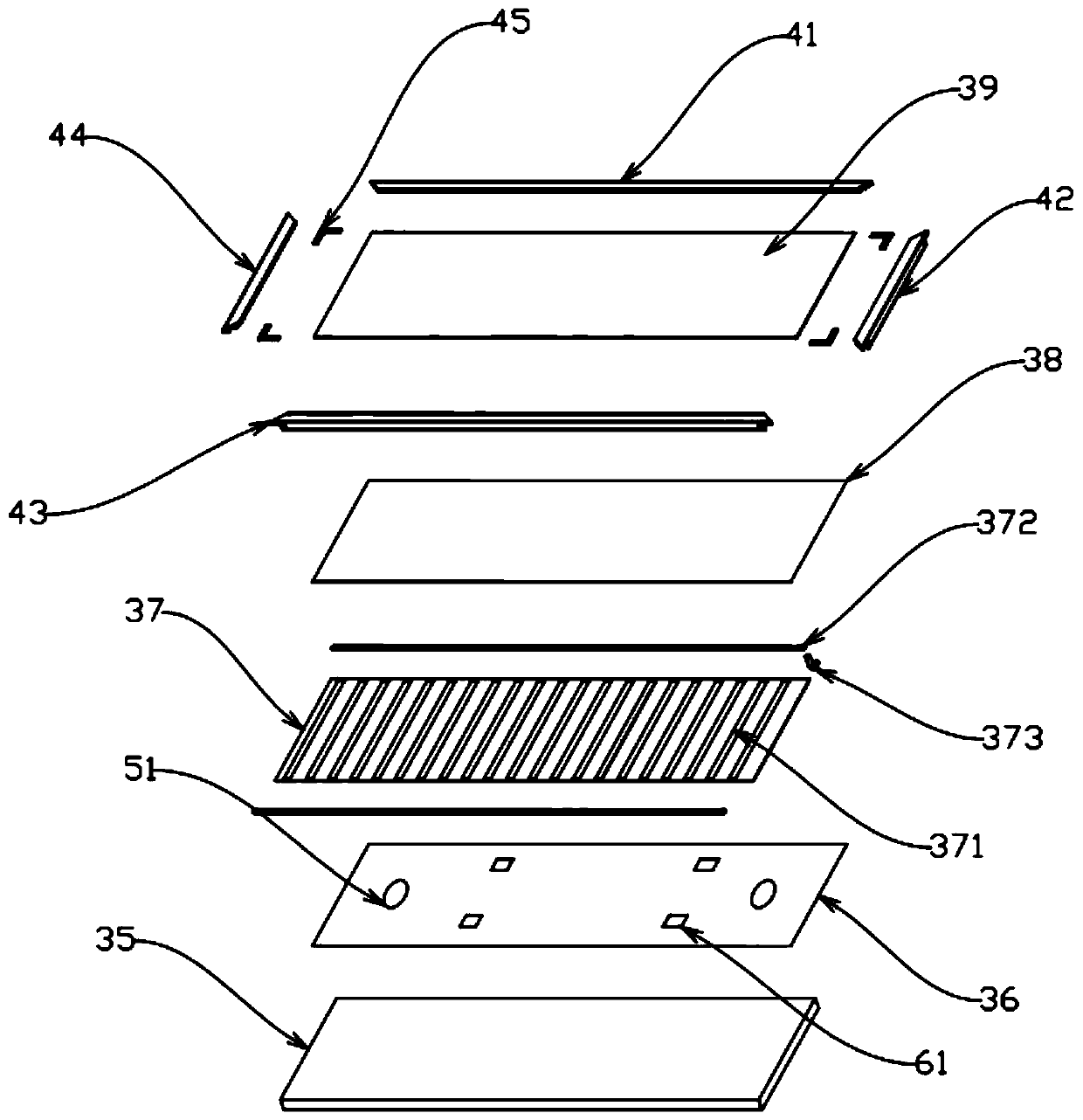
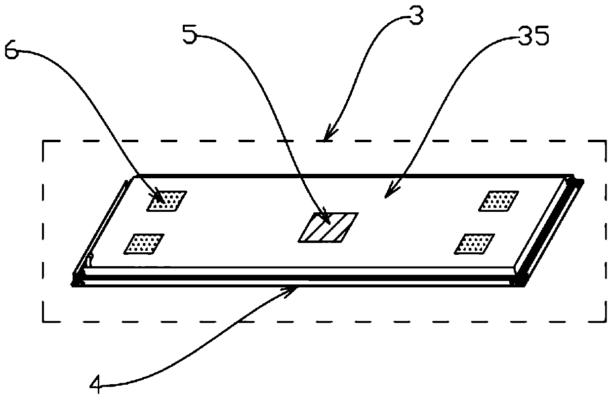
[0059] Similar to Example 1, the difference is only in the structure of the panel frame, such as Figure 4 with Figure 5 As shown, the panel frame 4 is welded by a number of connecting pieces 46. One edge of each connecting piece 46 protrudes upward to form a card 404 for connecting the keel, and the other edge is provided with an overlap joint for placing a heat insulation board 35. A groove 406 is provided between the two edges of the connecting member; the connecting member 46 and the heat insulation board 35 are firmly connected by a spring sheet 7, and one end of the spring sheet 7 is connected to the overlap plate 405 A accommodating space for the heat insulation board 35 is formed between the two ends, and the V-shaped structure at the other end is clamped into the groove 406 to clamp the heat insulation board 35 between the lap board 405 and the spring sheet 7. The V-shaped structure is picked out, and then the ceiling module unit 3 is removed from the panel frame 4.

[...


PUM


Abstract

The invention discloses a three-dimensional infrared radiation heating system. The heating system comprises a plurality of ceiling module units which are correspondingly arranged on a ceiling and walls, the ceiling is provided with a first heating module formed by combining the plurality of ceiling module units, a second heating module, a third heating module, a fourth heating module and a fifth heating module formed by the plurality of ceiling module units are correspondingly installed on the walls adjacent to the ceiling, and the first heating module, the second heating module, the third heating module, the fourth heating module and the fifth heating module are correspondingly and independently controlled. According to the system, the multi-block connection of the ceiling module units isadopted for effective combination, so that one or more directions can be controlled to heat, and then the overall heating of an indoor air environment is realized.

Description

Technical field [0001] The invention relates to the processing field of ceiling heating equipment, in particular to a three-dimensional infrared radiation heating system. Background technique [0002] At present, with the development of science and technology, the application of graphene has become more and more extensive. With the display of the excellent properties of graphene, more and more industries are developing the diverse use values ​​of graphene; in the existing technology, Graphene has become an ideal heating film material due to its excellent mechanical, electrical and optical properties. With the large-scale application of graphene heating film in the home appliance industry, its cost has also dropped significantly, and it has reached the golden age of civilian use. [0003] Common graphene heating film includes substrate, graphene film, conductive connection mesh, electrode and protective layer arranged in order from the bottom layer to the surface layer; the graphene...

Claims


Application Information

Patent Timeline
Patent Type & Authority Applications(China)
IPC IPC(8): F24D13/02F24D19/06H05B3/14H05B3/22
CPCF24D13/024F24D19/062F24D2200/08F24D2220/2081H05B3/145H05B3/22H05B2203/026
Inventor 王永麟姚松良陶东
Owner ZHEJIANG LAISIAO ELECTRIC
Features
  • Generate Ideas
  • Intellectual Property
  • Life Sciences
  • Materials
  • Tech Scout
  • Unparalleled Data Quality
  • Higher Quality Content
  • 60% Fewer Hallucinations
Learn More