Automatic grain turning and drying device for agriculture

An automatic turning and grain technology, applied in the field of grain, can solve the problems of turning and drying waste, reducing work efficiency, and complicating operating procedures, and achieving the effect of improving manpower and material resources and improving efficiency.

Inactive Publication Date: 2019-09-03
安徽省宝景生态农业科技有限公司
4 Cites 0 Cited by

AI-Extracted Technical Summary

Problems solved by technology

[0004] Aiming at the deficiencies of the prior art, the present invention provides an automatic grain drying device for agriculture, which solves the problem that the automatic grain drying device for agricultural use wastes a lot of manpower and material resources when turning grain...

Abstract

The invention discloses an automatic grain turning and drying device for agriculture. The automatic grain turning and drying device comprises a box body, wherein the left side and the right side of the bottom of the box body are fixedly connected with first rollers, the inside of the box body is rotatably connected with a turntable, one side of the turntable is fixedly connected with a first beltwheel through a first rotating shaft, the bottom of the box body is fixedly connected with second rollers, a first movable rod penetrates through the bottom of the box body, and the back surface of the second roller is fixedly connected with one end of the first movable rod through a first convex block. The device relates to the technical field of grains. According to the automatic grain turning and drying device for agriculture, the first movable rod and the second movable rod on the second roller are matched to rotate to drive rotation of the first belt wheel, the second belt wheel is drivento rotate through belt transmission, rotation of a second rotating shaft is matched with a turning piece to roll, so that grains can be turned and dried, the problem that the grain turning and dryingwastes large manpower and material resources is solved, and the turning efficiency is improved.

Application Domain

Lighting elementsDrying chambers/containers +5

Technology Topic

AgricultureMaterial resources +1

Image

  • Automatic grain turning and drying device for agriculture
  • Automatic grain turning and drying device for agriculture
  • Automatic grain turning and drying device for agriculture

Examples

  • Experimental program(1)

Example Embodiment

[0024] The technical solutions in the embodiments of the present invention will be clearly and completely described below in conjunction with the accompanying drawings in the embodiments of the present invention. Obviously, the described embodiments are only a part of the embodiments of the present invention, rather than all the embodiments. Based on the embodiments of the present invention, all other embodiments obtained by those of ordinary skill in the art without creative work shall fall within the protection scope of the present invention.
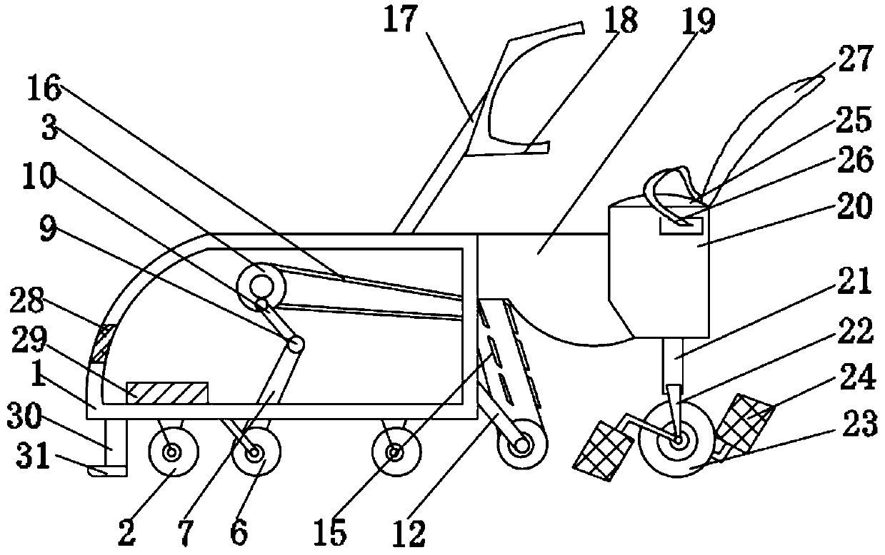
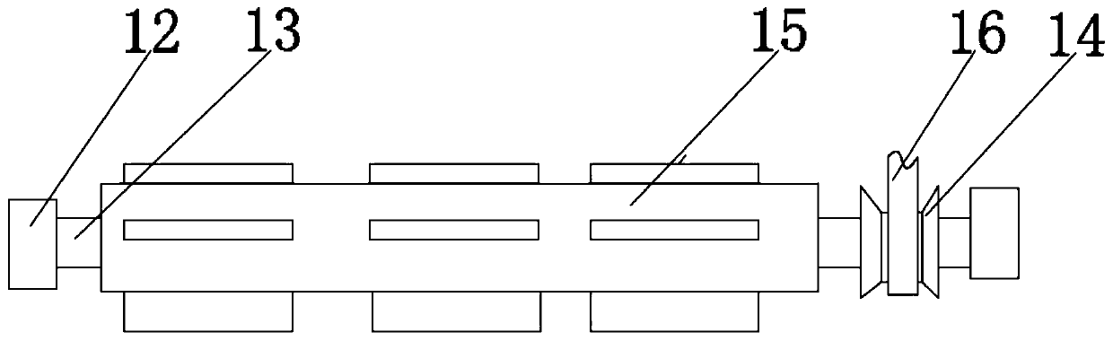
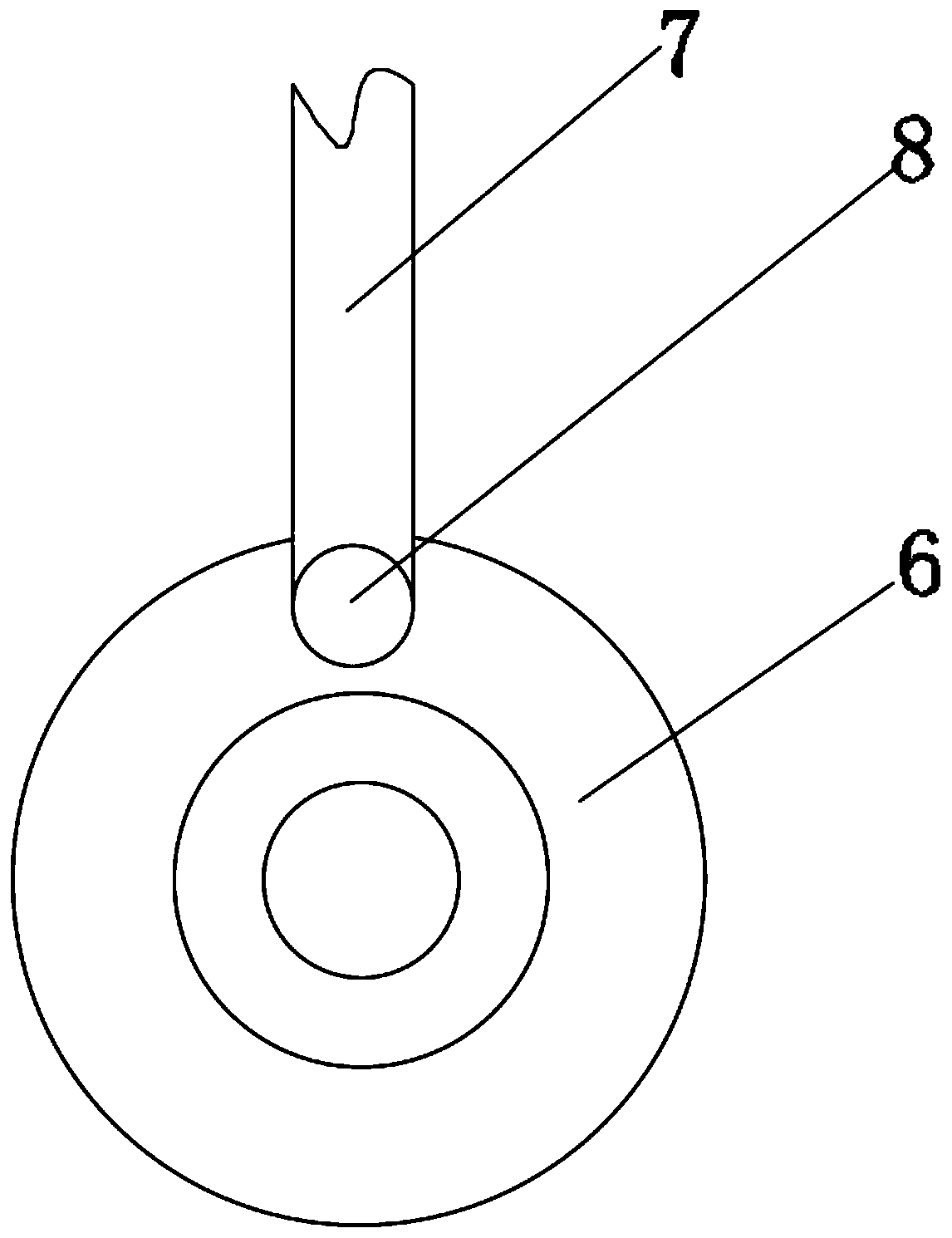
[0025] See Figure 1-4 , The present invention provides a technical solution: an automatic agricultural turning device for grains, comprising a box body 1, and an LED lamp 28 is fixedly connected to the inside on the right side of the box body 1. The LED lamp 28 and a lithium battery 29 can be used together Lighting in the dark in the evening can solve the problem of the dark working days of the operator in the evening. The inside of the box 1 is fixedly connected with a lithium battery 29, which is a type of lithium metal or lithium alloy As a negative electrode material, batteries using non-aqueous electrolyte solutions, proposed and started research on lithium ion batteries. Due to the very active chemical properties of lithium metal, the processing, storage and use of lithium metal have very high environmental requirements. With the development of science and technology, lithium batteries 29 have become the mainstream now, and lithium batteries 29 can be roughly divided into two categories. Lithium metal batteries and lithium ion batteries. Lithium-ion batteries do not contain metallic lithium and are rechargeable. The fifth generation of rechargeable batteries, lithium metal batteries, was born in 1996, and its safety, specific capacity, self-discharge rate, and cost performance are all superior to lithium-ion batteries. Due to its own high-tech requirements, only a few companies in a few countries are producing this kind of lithium metal battery. The bottom of the box 1 is fixedly connected with a fixing plate 30, and the fixing plate 30 and the steel block 31 are used together, so that you can Level the grains in front, do the preliminary work for the next step, integrate the machine, facilitate the operation of the operator and improve the efficiency of the work. The bottom of the fixed plate 30 is fixedly connected with a steel block 31, and the right side of the box 1 The second rotating shaft 13 is fixedly connected by the first bracket 12, the outer surface of the second rotating shaft 13 is fixedly connected with a second pulley 14, the outer surface of the second rotating shaft 13 is fixedly connected with a flap 15, and the outer surface of the first pulley 5 passes The belt 16 is drivingly connected to the outer surface of the second pulley 14. A steel column 17 is fixedly connected to the top of the box body 1, one end of the steel column 17 is fixedly connected to a handle 18, and a fixing block 19 is fixedly connected to the right side of the box body 1. The right side of the block 19 is fixedly connected with a stool block 20, and the top of the stool block 20 is fixedly connected with a sponge stool 25. Both the left and right sides of the stool block 20 are movably connected with a seat belt 26, and both sides of the seat belt 26 are movable It is connected to the stool block 20 and cooperates with the steel plate 21 and the third roller 23 under the stool block 20. The rotation of the foot pedal 24 is used, so that it can be moved by riding the tanning device. In order to improve the work efficiency, the use of the seat block 20, the backrest 27, and the seat belt 26 solves the problem of improving the safety and comfort of the operator. At the same time, it also improves the efficiency of the operator's work, which facilitates the protection of the operator’s physical safety. The seat belt 26 buckle is a buckle that can be installed in the seat belt 26 socket of the seat block 20. If the driver does not wear the seat belt 26, the seat belt 26 will not sound the alarm. This kind of buckle design theme is very diversified. In addition to the design according to the vehicle brand, cartoon characters, basketball or football team logos are all made into buckle patterns. The whole body seat belt 26, that is, the seat belt 26 covers the whole body and is equipped with a waist. Multiple suspension points on the chest and back. It can generally be disassembled into a half-length seat belt 26 and a chest seat belt 26. The biggest application of the full-body seat belt 26 is to enable rescuers to work in a "head down" manner without considering the safety belt 26 slipping off, such as in deep wells. In the rescue, rescuers need to go "head down" and get close to the trapped person. The half-length seat belt 26, that is, the seat belt 26 only covers the half body, generally the lower body, but like the chest seat belt 26, the seat belt 26 tension limiter accident occurs Later, the seat belt 26 has been tightened under the action of the pre-tightening device. But we hope that after the peak force has passed, the tension of the seat belt 26 will be immediately reduced to reduce the occupant's force. This special task is completed by the seat belt 26 tension limiter: on the seat belt 26 device, there is A pre-tightening device like the front of the seat belt 26. The seat belt 26 is wound underneath. The shaft core is a steel torsion bar. When the load reaches a predetermined condition, the torsion bar starts to twist, which is to a certain extent The seat belt 26 is relaxed, and the tension limit function of the seat belt 26 is realized for the protection of the upper body. Its use range is narrower than that of the full-body seat belt 26. It is generally used for seat suspension. The personal fall protection system is used to protect workers. A complete set of products necessary to be connected to a fixed point can completely prevent falling from a height or completely prevent this from happening. Using these products alone cannot provide protection against falling, but if these components can be very Good combination, then they will form a set of personal fall protection systems that are extremely important to workplace safety and the overall fall protection plan. Personal fall protection system products mainly include hanging points, hanging point connectors, and intermediate connectors , The whole body seat belt 26, under the joint action of the seat belt 26 pre-tensioning device and the seat belt 26 tension limiter, the protection capacity of the seat belt 26 has almost reached the ideal state. Seeing the spirit in the subtleties, the advanced safety belt 26 can indeed provide reliable safety protection for the occupants. The top of the seat block 20 is fixedly connected with a backrest 27, and the bottom of the seat block 20 is fixedly connected with a steel plate 21 and a steel plate 21. One side is rotatably connected with the third roller 23 through the second bracket 22, the left and right sides of the third roller 23 are rotatably connected with foot pedals 24, the bottom left and right sides of the box body 1 are fixedly connected with the first roller 2. The inside of the body 1 is rotatably connected with a turntable 3, one side of the turntable 3 is fixedly connected with a first pulley 5 through a first rotating shaft 4, and the bottom of the box 1 is fixedly connected with a second roller 6, which cooperates with the use of the second roller 6 on the second roller 6. A movable rod 7 and a second movable rod 10 rotate to drive the rotation of the first pulley 5, and the second pulley 14 is driven to rotate through the transmission of the belt 16, and the rotation of the second shaft 13 is used in conjunction with the flap 15 to roll, so that the The grains are turned over, which can solve the waste of heavy manpower and material resources in grain turning and improve the efficiency of turning. The bottom of the box 1 has a first movable rod 7, and the back of the second roller 6 passes through the first bump 8 and the first movable rod. One end of the first movable rod 7 is fixedly connected, one end of the first movable rod 7 is fixedly connected to the second movable rod 10 through the roller 9, and the front surface of the turntable 3 is fixedly connected to one end of the second movable rod 10 through the second protrusion 11.
[0026] When working, step on the foot pedal 24, the grain turning device will move, driving the second roller 9 to roll, and the second roller 9 will drive the first movable rod 7 and the second movable rod 10 to rotate. The rotation of the movable rod 10 drives the turntable 3 to rotate, the turntable 3 rotates to drive the first rotating shaft 4 to rotate, the first rotating shaft 4 rotates to drive the first pulley 5 to rotate, the rotation of the first pulley 5 drives the belt 16, and the belt 16 drives the second pulley 14 to rotate , The rotation of the second pulley 14 drives the rotation of the second shaft 13, and the rotation of the second shaft 13 drives the flap 15 to rotate, so that the grain can be turned over. The seat belt 26 and the backrest 27 on the seat block 20 affect the operator's body The safety is protected. The steel block 31 on the fixed plate 30 can smooth the grain when the grain turning device moves. The LED lamp 28 on the box body 1 illuminates in the evening or night.
[0027] It should be noted that in this article, relational terms such as first and second are only used to distinguish one entity or operation from another entity or operation, and do not necessarily require or imply one of these entities or operations. There is any such actual relationship or order between. Moreover, the terms "include", "include" or any other variants thereof are intended to cover non-exclusive inclusion, so that a process, method, article or device including a series of elements not only includes those elements, but also includes those that are not explicitly listed Other elements of, or also include elements inherent to this process, method, article or equipment.
[0028] Although the embodiments of the present invention have been shown and described, those of ordinary skill in the art can understand that various changes, modifications, and substitutions can be made to these embodiments without departing from the principle and spirit of the present invention. And variations, the scope of the present invention is defined by the appended claims and their equivalents.

PUM

no PUM

Description & Claims & Application Information

We can also present the details of the Description, Claims and Application information to help users get a comprehensive understanding of the technical details of the patent, such as background art, summary of invention, brief description of drawings, description of embodiments, and other original content. On the other hand, users can also determine the specific scope of protection of the technology through the list of claims; as well as understand the changes in the life cycle of the technology with the presentation of the patent timeline. Login to view more.

Similar technology patents

Systems and methods for notifying multiple hosts from an industrial controller

ActiveUS8150959B1reusable block of code very difficultimprove efficiency
Owner:ROCKWELL AUTOMATION TECH

MIMO-OFDM transmitter

InactiveUS20070253504A1improve efficiencyreduce time
Owner:FUJITSU LTD

Systems and methods for providing treatment planning

InactiveUS20050182654A1high quality of careimprove efficiency
Owner:ALIGN TECH

Classification and recommendation of technical efficacy words

  • Improve efficiency
Why Eureka
Try Eureka