
Automatic height adjusting device based on laser displacement sensor and control method thereof

A laser displacement and control method technology, applied in laser welding equipment, manufacturing tools, welding equipment, etc., can solve the problems of unsuitable application of precision cutting control, low precision of Z-axis dynamic adjustment, unusable contact sensors, etc., to achieve Improve operating efficiency, ensure cutting accuracy and effect, and effect of long detection distance

Pending Publication Date: 2019-09-06
深圳市睿达科技有限公司
View PDF3 Cites 6 Cited by
  • Summary
  • Abstract
  • Description
  • Claims
  • Application Information

AI Technical Summary

Problems solved by technology

The beneficial effects of the above invention can be used for the processing height adjustment of non-metallic materials. The contact resistance sensor is used to obtain the height points of a limited number of processed workpieces by means of pre-acquisition, and the method of data interpolation is used to output Z during the cutting process. The adjustment value of the axis, but it cannot adjust the height of the Z-axis in real time according to the detected height of the workpiece; in addition, for some flexible materials or soft materials, the contact sensor will not be available; in addition, due to the use of In the pre-acquisition method, the processing efficiency will be greatly reduced. Finally, due to the limited number of collected data points, the accuracy of Z-axis dynamic adjustment is relatively low, which is not suitable for some precision cutting control applications.

Method used


Image

  • Automatic height adjusting device based on laser displacement sensor and control method thereof
  • Automatic height adjusting device based on laser displacement sensor and control method thereof
  • Automatic height adjusting device based on laser displacement sensor and control method thereof

Examples


Embodiment Construction

[0036] In order to make the object, technical solution and advantages of the present invention clearer, the present invention will be further described in detail below in conjunction with the accompanying drawings and embodiments. It should be understood that the specific embodiments described here are only used to explain the present invention, not to limit the present invention.

[0037] Technical scheme of the present invention is as follows:

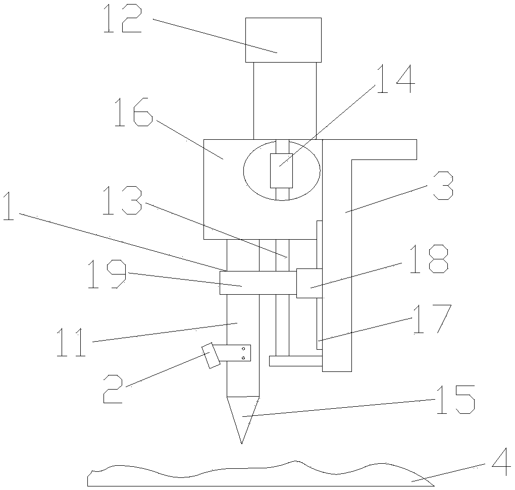
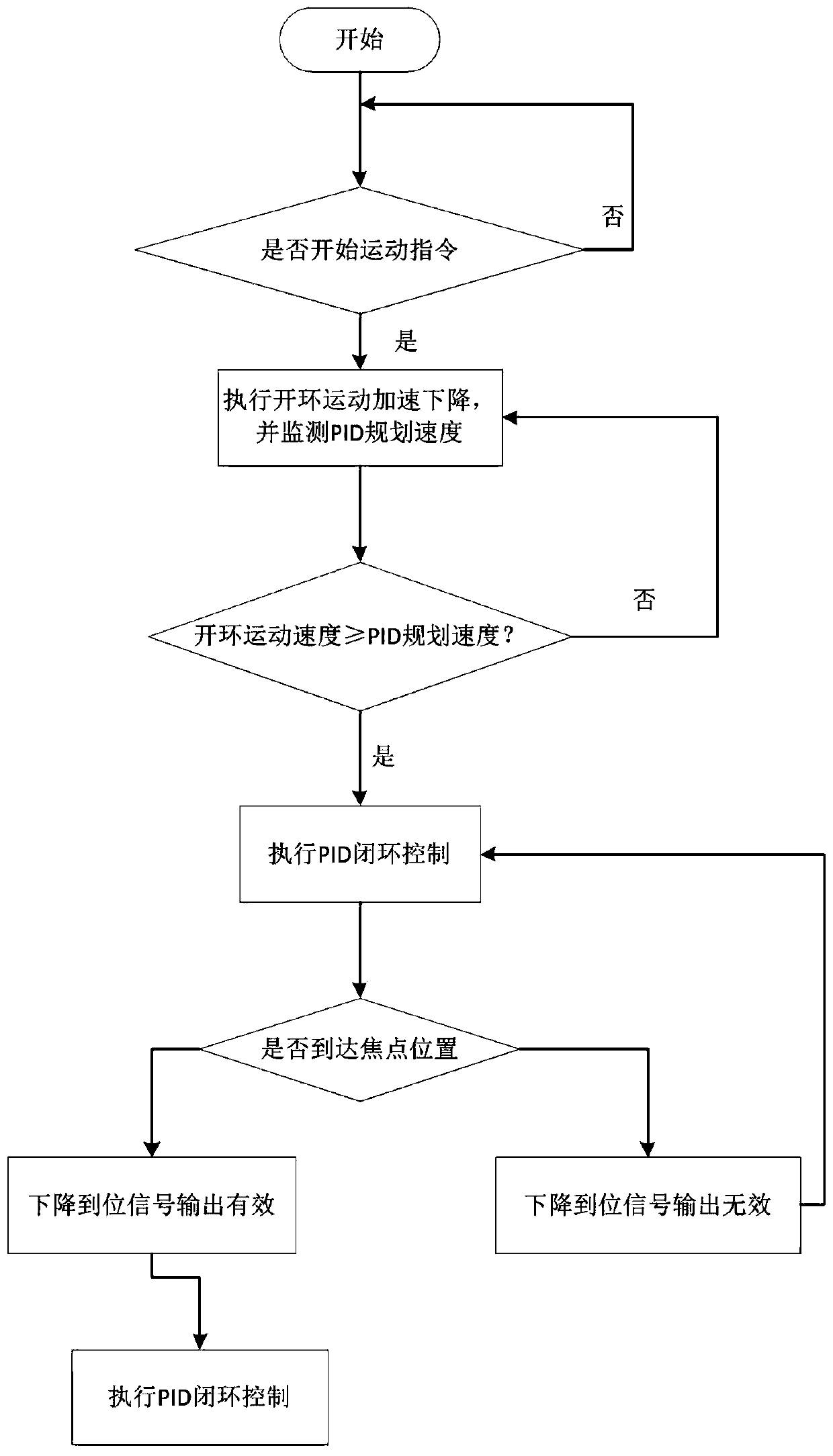
[0038] Such as Figure 1-3 , the present invention provides an automatic height adjustment device based on a laser displacement sensor, including a Z-axis motor actuator 1, a height adjustment controller (not shown) and a laser displacement sensor 2; the Z-axis actuator 1 includes a laser cutting head 11, Z-axis motor 12, leading screw 13 and leading screw nut 14; Z-axis motor 12 is fixed on the external frame 3, and is electrically connected with the height adjustment controller, and is controlled by the height adjustment controlle...


PUM


Abstract

The invention discloses an automatic height adjusting device based on a laser displacement sensor. The device comprises a Z-axis motor executing mechanism, a height adjusting controller and the laserdisplacement sensor. The automatic height-adjusting device is simple in structure. The laser displacement sensor examines the position of a workpiece and feeds back a distance signal, and the height adjusting controller then adjusts the height position of a laser cutting head according to a measurement feedback result. According to the device, the laser displacement sensor of Panasonic HG-C1100 model is adopted preferably, so that the detection precision is high. In addition, in the process of adjusting the height of the laser cutting head, the distances from positions of measuring spots of the laser displacement sensor to the cut workpiece are kept consistent, so that a purpose that a laser focusing point does not deviated from the cut workpiece. The invention also provides a control method of the automatic height adjusting device based on the laser displacement sensor. By collecting information of points in real time, the automatic height adjusting device carries out real-time control, so that the control precision is improved effectively and the operating efficiency of the whole system is improved.

Description

technical field [0001] The invention belongs to the field of laser processing, and in particular relates to an automatic height adjustment device of a laser cutting machine and a control system and method thereof. Background technique [0002] Ordinary two-dimensional laser cutting processing is generally composed of a laser, a mirror and a focusing mirror. The laser focus is focused on a two-dimensional plane for cutting. But when encountering uneven or three-dimensional processing materials, ordinary two-dimensional cutting systems will not be able to meet the cutting requirements. Laser cutting technology has the characteristics of high cutting dimensional accuracy, no burr in the incision, no deformation in the slit, fast cutting speed and not limited by the processing shape. It has been more and more used in the field of mechanical processing. [0003] When the cutting machine is in operation, in order to ensure that the distance between the cutting nozzle of the cutti...

Claims


Application Information

Patent Timeline
IPC IPC(8): B23K26/38B23K26/70
CPCB23K26/38B23K26/70B23K26/702
Inventor 肖成柱孙帅华靳超凡
Owner 深圳市睿达科技有限公司
Learn More