Sheet penetrating type double-layer-pipe pipe shell type heat exchanger

A heat exchanger, double-layer technology, applied in the direction of heat exchanger types, heat exchanger shells, indirect heat exchangers, etc., can solve the problem of affecting the service life of heat exchangers, low finning ratio of heat exchange elements, and inability to pull cores. Overhaul and maintenance, etc., to achieve the effect of convenient cleaning and maintenance, low wing-to-fing ratio, and core-pulling overhaul and maintenance

Pending Publication Date: 2019-09-06
DONGFANG ELECTRIC MACHINERY
View PDF0 Cites 0 Cited by
  • Summary
  • Abstract
  • Description
  • Claims
  • Application Information

AI Technical Summary

Problems solved by technology

[0005] However, the heat exchange tubes of traditional double-tube heat exchangers use bare tubes or low-fin enhanced heat transfer tubes. The heat exchange element has a low fin ratio, the heat exchange area per unit volume of the heat exchanger is small, the heat exchange efficiency is low, and the manufacturing cost is high.
At the same time, the traditional structure of the double-tube heat exchanger is mostly a fixed tube-sheet structure, and the heat exchanger shell and the tube plate are fixed by welding, which cannot be checked and maintained by core pulling, which affects the service life of the heat exchanger

Method used


Image

  • Sheet penetrating type double-layer-pipe pipe shell type heat exchanger
  • Sheet penetrating type double-layer-pipe pipe shell type heat exchanger
  • Sheet penetrating type double-layer-pipe pipe shell type heat exchanger

Examples


Embodiment 1

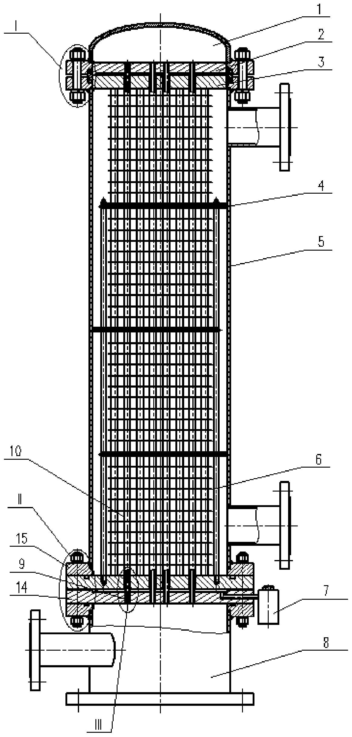
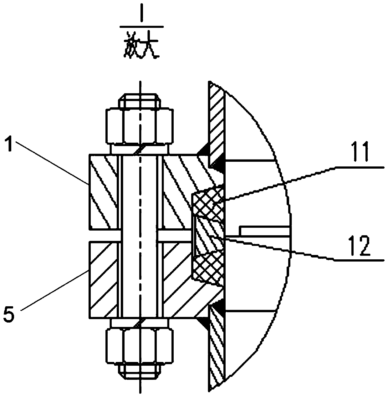
[0038] like figure 1As shown, in this embodiment, a pierced double-layer tube shell-and-tube heat exchanger is provided, and a heat exchanger core group with an integral structure is arranged inside it. Compared with the traditional double-layer tube heat exchanger The fixed tube-sheet structure is mostly adopted, and the heat exchanger shell 5 and the bearing tube plate are fixed by welding, which can compensate and eliminate the stress caused by the temperature difference between the heat exchanger shell 5 and the heat exchanger core group, and can also realize core-pulling inspection and maintenance. It greatly facilitates the cleaning and maintenance of the heat exchanger and prolongs its service life.

[0039] It includes a shell 5, an upper water chamber 1 and a lower water chamber 8, and also includes a heat exchanger core group, which includes an upper end tube plate assembly, a heat exchange tube assembly and a lower end tube plate assembly. The two ends of the heat ...

Embodiment 2

[0048] On the basis of Example 1, in order to further improve the heat conduction capacity inside the heat exchange tube, a whole sheet-through-sheet double-composite double tube structure is adopted, the details are as follows:

[0049] Such as Figure 5-Figure 7 As shown, a plurality of tube holes are opened on the heat sink 6, and each tube hole is respectively socketed with each outer heat exchange tube 10, and a plurality of fan-shaped arcs are distributed around each tube hole along the same circumferential direction. A plurality of fan-shaped arc-shaped openings 16 form a flow-disturbing structure, which can change the state of the medium passing over the heat sink 6 from a laminar flow state to a turbulent flow, increasing the eddy flow of the heat exchange medium The vortex strength makes the heat conduction more sufficient. Preferably, in this embodiment, the cooling fin 6 is continuously punched and formed on the entire copper strip using a high-precision mold, whi...

Embodiment 3

[0052] On the basis of Example 1, in order to further improve the safety performance of the heat exchange tube, the following improvements are made:

[0053] Such as Figure 8 As shown, a plurality of penetrating lyophobic grooves are formed on the inner wall of the outer heat exchange tube 10 , and each lyophobic groove is in a spiral shape. The length of each of the lyophobic grooves is equal to the length of the outer heat exchange tube 10. Since the inner heat exchange tube 9 and the outer heat exchange tube 10 are bonded by a composite tube process, after bonding, each of the lyophobic grooves The liquid grooves are located between the inner heat exchange tube 9 and the outer heat exchange tube 10 .

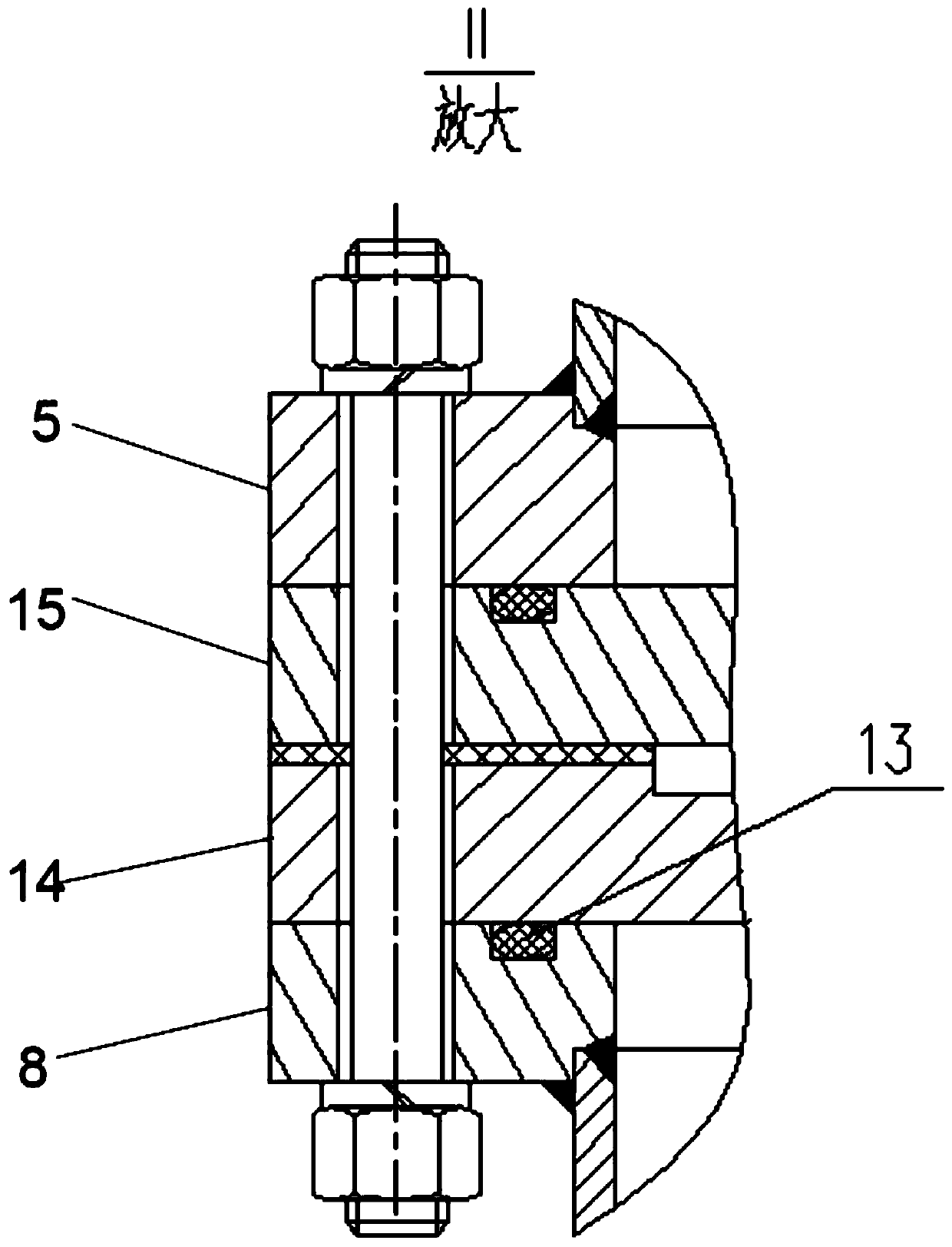
[0054] On the surface of the outer bearing tube plate 14 at the lower end, a liquid accumulation chamber 17 is opened, which corresponds to each of the liquid-repellent grooves, and the liquid accumulation chamber 17 is connected with a leakage alarm 7, and the leakage alar...


PUM


Abstract

The invention discloses a sheet penetrating type double-layer-pipe pipe shell type heat exchanger and belongs to the technical field of electric power, petrochemical and thermal power engineering. A heat exchanger core set of an integrated structure is arranged in the sheet penetrating type double-layer-pipe pipe shell type heat exchanger; the lower end of the heat exchanger core set is fixed, andthe upper end of the heat exchanger core set adopts a floating structure; meanwhile, the upper floating end of the heat exchanger core set is in movable sealing sleeved connection by adopting a structure of a trapezoidal sealing ring; the lower fixed end of the heat exchanger core set is sealed and assembled through a 0-shaped sealing ring structure; the stress generated by a heat exchanger shelland the heat exchanger core set due to a temperature difference can be compensated for and eliminated; core pulling overhauling and maintaining can also be achieved, and cleaning and maintaining of the heat exchanger are greatly facilitated; by adopting a whole piece of sheet penetrating type cooling fin, the heat exchanging area of a cooler is increased, the volume of the heat exchanger can be effectively decreased, the comprehensive performance of the heat exchanger is improved, and the manufacturing cost of the double-layer-pipe heat exchanger is lowered; and by adopting a double-layer-pipe structure of double pipe plates, a liquid dredging groove is formed in the inner wall of an outer heat exchanging pipe of the heat exchanger, a lower end outer bearing pipe plate is provided with aliquid accumulating cavity, the liquid accumulating cavity triggers a leaking alarming device to give an alarm, and the using safety is improved.

Description

technical field [0001] The invention belongs to the technical field of electric power, petrochemical and thermal energy engineering, and specifically relates to a piercing type double-layer tube-shell heat exchanger. Background technique [0002] Shell and tube heat exchanger is also called shell and tube heat exchanger. It is a partitioned wall heat exchanger that uses the wall of the tube bundle enclosed in the shell as the heat transfer surface. This kind of heat exchanger has simple structure, low cost, wide flow cross-section, and easy to clean scale; but it has low heat transfer coefficient and occupies a large area. It can be made of various structural materials (mainly metal materials), and can be used under high temperature and high pressure. It is the most widely used type at present. [0003] In the prior art, the heat exchange tubes of shell and tube heat exchangers mostly use single-layer tubes. When the heat exchanger is working, the heat exchange medium (wat...

Claims


Application Information

Patent Timeline
IPC IPC(8): F28D7/16F28F9/24F28F9/04F28F9/18F28F27/00F28F1/10
CPCF28D7/16F28F9/24F28F9/04F28F9/18F28F27/00F28F1/10
Inventor 王万才周春兰袁绍斌张梅李忠华
Owner DONGFANG ELECTRIC MACHINERY
Why Eureka
Try Eureka