
Waste heat utilization system of well air

A waste heat and air duct technology, applied in mine/tunnel ventilation, indirect heat exchangers, lighting and heating equipment, etc., can solve problems such as the inability to meet the needs of non-heating seasons in summer, prevent dust accumulation, enhance disturbance, Indestructible effect

Pending Publication Date: 2019-09-06
国能龙源蓝天节能技术有限公司上海分公司
View PDF0 Cites 3 Cited by
  • Summary
  • Abstract
  • Description
  • Claims
  • Application Information

AI Technical Summary

Problems solved by technology

Therefore, the air duct layout under the existing heat pipe heat exchange system for underground return air cannot meet the needs of non-heating seasons in summer

Method used


Image

  • Waste heat utilization system of well air
  • Waste heat utilization system of well air

Examples


Embodiment Construction

[0031] The present invention will be described in detail with reference to the accompanying drawings and examples. Each example is provided by way of explanation of the invention, not limitation of the invention. In fact, those skilled in the art will recognize that modifications and variations can be made in the present invention without departing from the scope or spirit of the invention. For example, features illustrated or described as part of one embodiment can be used on another embodiment to yield a still further embodiment. Therefore, it is intended that the present invention includes such modifications and variations as come within the scope of the appended claims and their equivalents.

[0032] In the description of the present invention, the terms "longitudinal", "transverse", "upper", "lower", "front", "rear", "left", "right", "vertical", "horizontal", " The orientations or positional relationships indicated by "top", "bottom", etc. are based on the orientations ...


PUM


Abstract

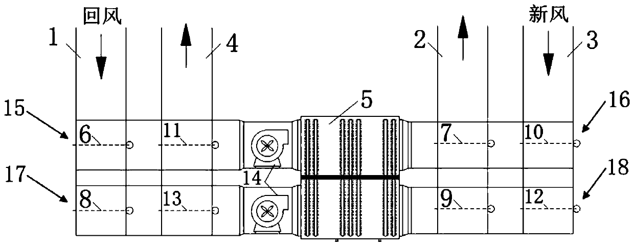
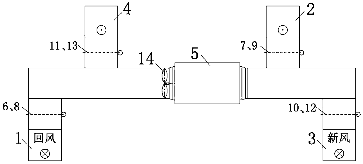
The invention provides a waste heat utilization system of well air. The system comprises a return air inlet path, a return air exhaust path, a fresh air inlet path, a fresh air exhaust path, a heat exchanger, axial-flow fans and valves, wherein the return air inlet path and the fresh air exhaust path are connected to one end of a first air flue and one end of a third air flue, and joints are equipped with valves; the other end of the first air flue and the other end of the third air flue are connected to the heat exchanger; the return air inlet path, the return air exhaust path and the fresh air inlet path are connected to one end of a second air flue and one end of a fourth air flue, and joints are equipped with valves; the other end of the second air flue and the other end of the fourthair flue are connected to the heat exchanger; and the axial-flow fans are arranged in the first air flue and the third air flue and / or the second air flue and the fourth air flue. The system recycleswaste heat in underground return air in winter to preheat air flues for fresh air circulation. In summer, return air is used as a cold source through valve conversion, so that the effects of cooling the air flues for fresh air circulation and reducing heat damages are reduced.

Description

technical field [0001] The invention relates to the technical field of energy saving, in particular to a well wind waste heat utilization system of an underground well. Background technique [0002] The heat pipe heat exchange system for well wind is specially developed for recovering the low-temperature waste heat of underground return air. Heating methods such as power consumption reduce operating costs and achieve energy saving and emission reduction. The system can replace the low-temperature residual heat of the downhole return air above 10°C, ensuring that the inlet air temperature at the wellhead is 2°C to 4°C in winter, meeting the antifreeze requirements of the wellhead. [0003] The existing underground return air heat pipe heat exchange system is provided with a fresh air inlet channel, a return air inlet channel, a fresh air outlet channel, a return air outlet channel, a heat pipe heat exchanger and an explosion-proof axial flow fan. [0004] In the winter heat...

Claims


Application Information

Patent Timeline
Patent Type & Authority Applications(China)
IPC IPC(8): F28D15/02E21F1/00E21F1/04E21F1/08
CPCF28D15/0266E21F1/00E21F1/04E21F1/08
Inventor 钟震周予民冯海波王军袁汉川袁志先谭茹吴俊杰季薇王雪平潘翠翠许祥训张尚云吕静
Owner 国能龙源蓝天节能技术有限公司上海分公司
Learn More