Continuous traction power supply system of electrified railway and fault section identification method thereof

A traction power supply system and electrified railway technology, applied in power lines, fault locations, fault detection by conductor type, etc., can solve problems such as increasing investment, passive situation, affecting power quality, etc., to achieve rapid fault isolation and improve reliability. , Economical effect

Inactive Publication Date: 2019-09-06
SOUTHWEST JIAOTONG UNIV
View PDF13 Cites 5 Cited by
  • Summary
  • Abstract
  • Description
  • Claims
  • Application Information

AI Technical Summary

Problems solved by technology

[0003] However, since the traction load of each section cannot be the same at any time, the phase-splitting and segmenting scheme only alleviates the impact of three-phase imbalance to a certain extent, and does not fundamentally solve the impact of single-phase power consumption of railway loads on the entire public grid. influences
Due to problems affecting power quality, electrified railways are forced to modify the design plan and increase investment, and the passive situation often occurs
[0004] At the same time, due to the existence of the electric phase separation device, when the locomotive runs to the end of a power supply section, it must go through a series of complex operations such as downgrading and power failure, and then slide to the next section and then resume normal operation one by one. It increases the complexity of locomotive operation, and at the same time seriously restricts the improvement of locomotive running speed and the exertion of traction

Method used


Image

  • Continuous traction power supply system of electrified railway and fault section identification method thereof
  • Continuous traction power supply system of electrified railway and fault section identification method thereof

Examples


Embodiment 1

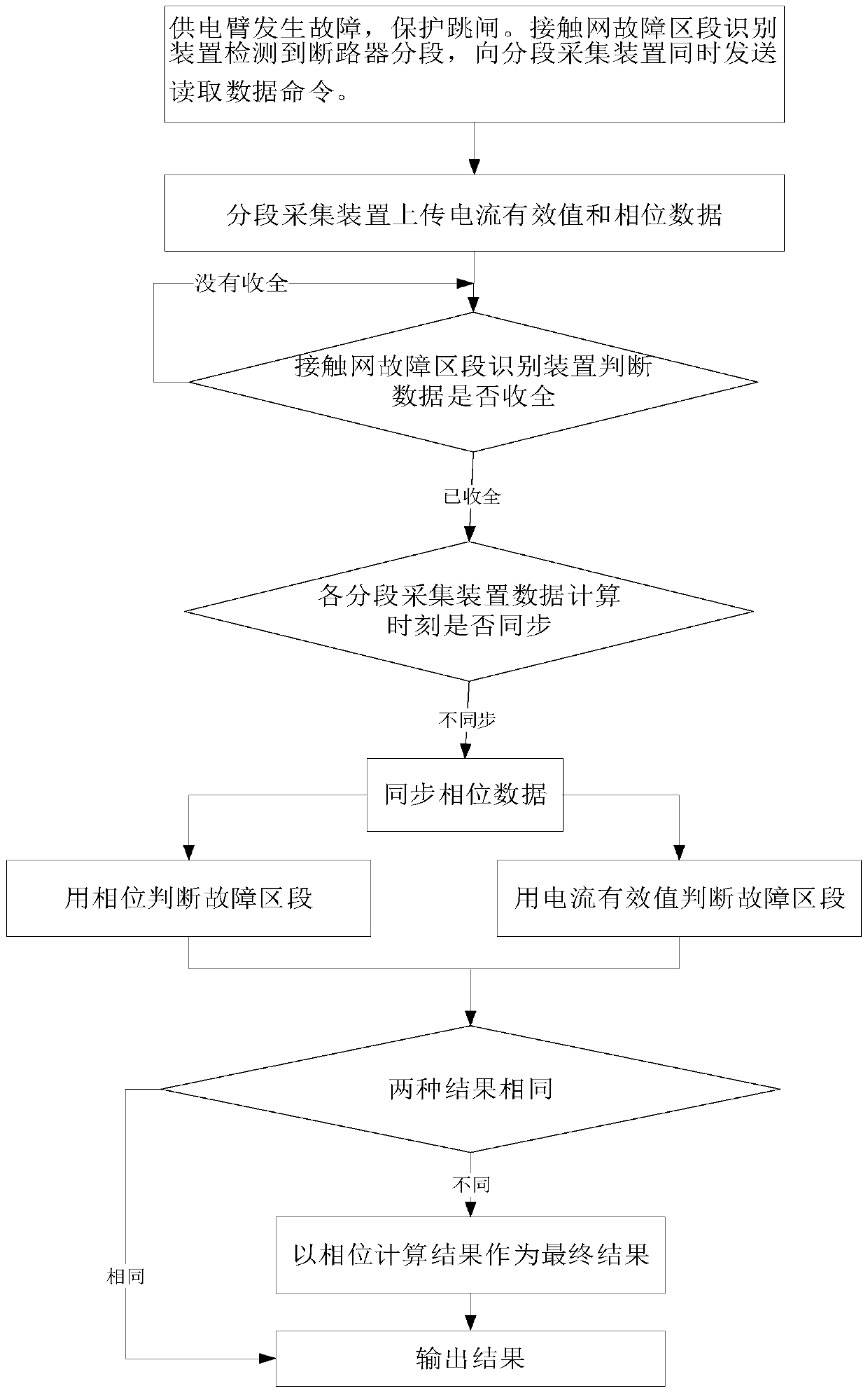
[0023] Such as figure 2 As shown, the embodiment of the present invention is a method for identifying the fault section of the through-traction power supply system of an electrified railway. The catenary fault section identification device of the system sends the read data command to each section segment acquisition device at the same time, and remembers the time t1 of sending the command; each segment acquisition device remembers the current time t after receiving the read data command, and Upload the current effective value and the phase relative to the current time t recorded in the time period Tm from the current time t to the current time t to the catenary fault section identification device of the power supply system; the catenary fault section of the power supply system After the identification device collects all the data of the acquisition device in each segment, use the effective value and phase of the two cycles after the moment when the sudden increase in effectiv...

Embodiment 2

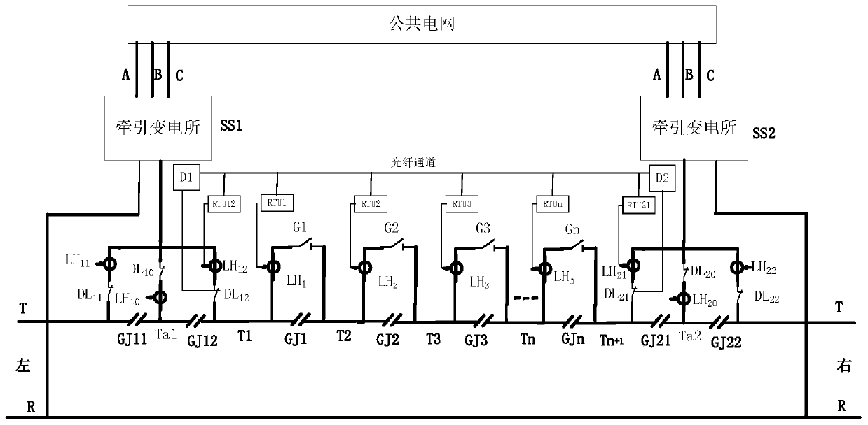
[0030] Such as figure 2 As shown, a power supply system for electrified railway through traction, the electrified railway through traction power supply system includes at least two traction substations and catenary T and rail R in the section under their jurisdiction, each traction substation is respectively Connected with catenary T and rail R, two adjacent traction substations are marked as traction substation SS1 and traction substation SS2 from left to right; the contact between traction substation SS1 and traction substation SS2 The network is divided into n+1 power supply sections, n≧2; the two power supply sections are separated by a segmenter, which are marked as section T1, section T2, section T3,..., section Tn, section Tn+ 1; The sectionalizer set between section T1 and section T2 is marked as GJ1, the sectionalizer set between section T2 and section T3 is marked as GJ2, ..., section Tn and section Tn+ The sectionalizer provided between 1 is marked as GJn, and in ...


PUM


Abstract

The invention, which belongs to the technical field of traction power supply of an electrified railway, discloses a continuous traction power supply system of an electrified railway and a fault section identification method thereof. When a fault occurs in a bilateral power supply overhead line system and an existing protection device of a traction substation trips to cut off the fault, a fault section identification device of a traction power supply system overhead line system sends data reading instructions to all section collection devices and records an instruction sending time t1; and allsection collection devices records a current time t after reading the data instructions, and a current effective value recorded within a range of from the current time to a period Tm of time before current time t as well as a phase relative to the current time t is uploaded to an overhead line system fault section identification device. After the overhead line system fault section identification device collects data from all section collection devices, a fault section is determined by using effective values and phases of two cycles after the sudden increasing occurrence time of the effective value.

Description

technical field [0001] The invention belongs to the technical field of AC electrified railway traction power supply. Background technique [0002] The single-phase system has the advantages of simple structure, low construction cost, convenient operation and maintenance, etc., which determines that single-phase power frequency AC power is generally used to power railway locomotives in electrified railways. The power system hopes that all loads will use the three-phase symmetrical fundamental current from the power grid to make full use of the capacity of equipment and lines and reduce the harm of reactive current and harmonic current to the system. In order to meet this requirement, the electrified railway adopts the scheme of phase sequence rotation and phase-by-phase power supply. Every 20-25km along the railway line is used as a power supply section, and each section is powered by different phases in the power grid in turn. A phase separation section of about 30m is set,...

Claims


Application Information

Patent Timeline
Patent Type & Authority Applications(China)
IPC IPC(8): G01R31/08B60M3/00
CPCB60M3/00G01R31/086
Inventor 易东李群湛李晋解绍锋林志海郭锴王继来王帅黄文勋
Owner SOUTHWEST JIAOTONG UNIV
Why Eureka
Try Eureka