
Display panel and manufacturing method thereof

A technology for display panels and manufacturing methods, applied in optics, instruments, electrical components, etc., can solve problems that affect flatness and cannot maintain a flat state, and achieve the effect of shortening the production cycle

Inactive Publication Date: 2019-09-06
WUHAN CHINA STAR OPTOELECTRONICS TECH CO LTD
View PDF5 Cites 0 Cited by
  • Summary
  • Abstract
  • Description
  • Claims
  • Application Information

AI Technical Summary

Problems solved by technology

[0003] However, the low-temperature polysilicon array substrate of the existing liquid crystal display will have a light-shielding layer (LS) under the thin film transistor, and the light-shielding layer will affect the flatness under the semiconductor channel region of the thin film transistor, so that it cannot maintain a completely flat state

Method used


Image

  • Display panel and manufacturing method thereof
  • Display panel and manufacturing method thereof
  • Display panel and manufacturing method thereof

Examples


Embodiment Construction

[0044] The preferred embodiments of the present invention will be described in detail below in conjunction with the accompanying drawings, to fully introduce the technical content of the present invention to those skilled in the art, to prove that the present invention can be implemented, to make the technical content disclosed in the present invention clearer, and to make the technical content of the present invention clearer. It is easier for those skilled in the art to understand how to implement the present invention. However, the present invention can be realized through many different forms of embodiments, and the scope of protection of the present invention is not limited to the embodiments mentioned herein, and the descriptions of the following embodiments are not intended to limit the scope of the present invention.

[0045] The directional terms mentioned in the present invention, such as "up", "down", "front", "back", "left", "right", "inside", "outside", "side", etc...


PUM


Abstract

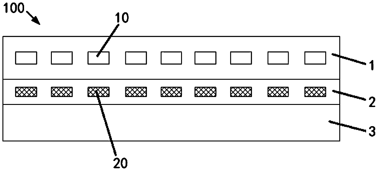
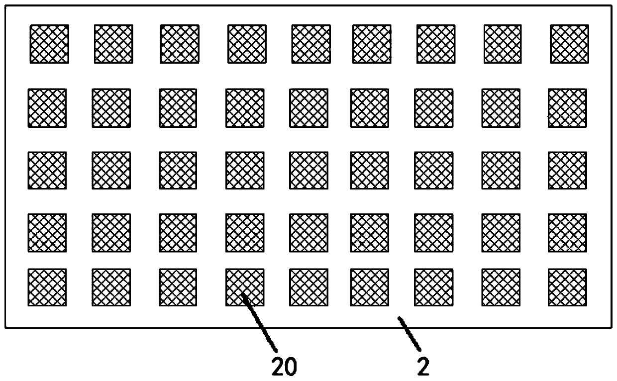
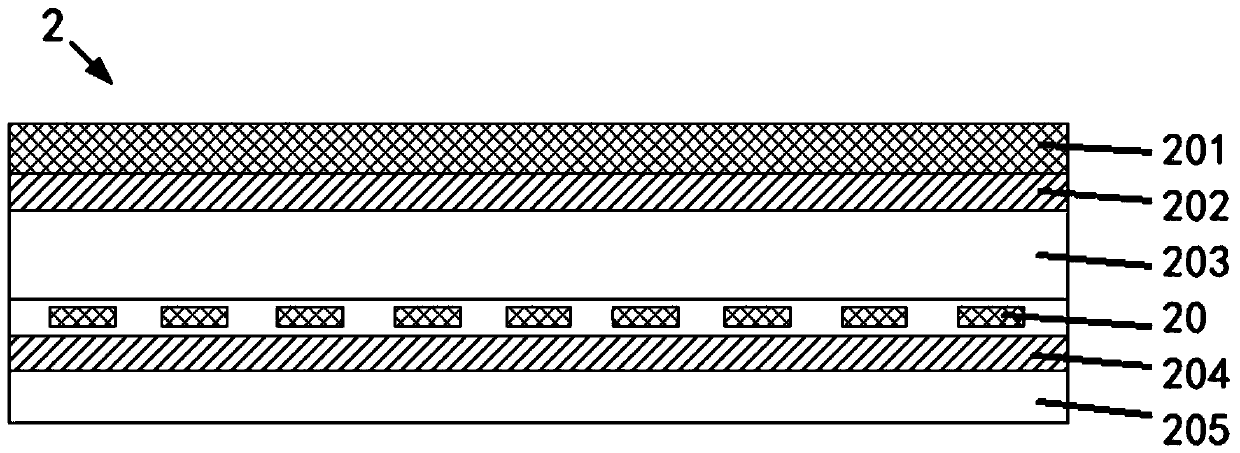
The invention provides a display panel and a manufacturing method thereof. The display panel comprises an array substrate, a backlight source and an array substrate polarizer. The array substrate hasmultiple thin film transistors; the backlight source is arranged under the array substrate and is used for providing a light source; and the array substrate polarizer is arranged to the side, facing to the backlight source, of the array substrate, and has light shielding portions, wherein the light shielding portions are corresponding to the thin film transistors. The manufacturing method of the display panel comprises the following steps: preparing the array substrate; preparing the array substrate polarizer; attaching the array substrate polarizer; and attaching the backlight source. By removing a shielding layer (LS) on an existing array substrate, flatness of the lower portion of a semiconductor channel region of the thin film transistor is maintained; by adding the light shielding portions onto the array substrate polarizer corresponding to the thin film transistors, the semiconductor channel region of the thin film transistor can be prevented from being influenced by light; and production cost and time can be saved.

Description

technical field [0001] The invention relates to the display field, in particular to a display panel and a manufacturing method thereof. Background technique [0002] At present, the array substrate of low-temperature polysilicon (LTPS) products is composed of a separate switching element thin film transistor (Thin Film Transistor, TFT), a storage capacitor (Cst) and a pixel transparent electrode (Pixel Electrode). The semiconductor performance of the thin film transistor is enhanced by ion implantation. Under the action of the electric field of the scanning line (Gate), the charging and discharging process of the pixel transparent electrode (Pixel Electrode) is realized, and the voltage of the plate under the storage capacitor (Cst) is adjusted to control the rotation angle of the liquid crystal molecules, so as to realize the colorful display effect of the liquid crystal display product . [0003] However, the low-temperature polysilicon array substrates of the existing li...

Claims


Application Information

Patent Timeline
Patent Type & Authority Applications(China)
IPC IPC(8): H01L27/12H01L29/786G02F1/1362G02F1/1335
CPCH01L27/1248H01L29/78633H01L27/1262G02F1/136209G02F1/136227G02F1/133528G02F2202/104G02F1/1362G02F1/13685G02F1/133512G02F1/133567G02F2202/28
Inventor 余朋飞
Owner WUHAN CHINA STAR OPTOELECTRONICS TECH CO LTD
Learn More