
Permanent-magnet motor rotor core structure

A rotor core, permanent magnet motor technology, applied in the shape/style/structure of the magnetic circuit, the rotating parts of the magnetic circuit, the magnetic circuit, etc., can solve the high risk of rotor fragmentation, increase the difficulty of punching, increase the reluctance, etc. problems, to reduce the risk of high temperature demagnetization, weaken the magnetic flux leakage phenomenon, and reduce costs.

Inactive Publication Date: 2019-09-06
ANHUI UNIVERSITY
View PDF10 Cites 0 Cited by
  • Summary
  • Abstract
  • Description
  • Claims
  • Application Information

AI Technical Summary

Problems solved by technology

In the process of patent implementation, the combination and lamination process of the first punch and the second punch is complicated, and the factory operation is difficult
In order to cut off the magnetic circuit for the first punching piece, the size of the main body and the inner ring of the punching piece must be reduced to increase the magnetic resistance, which increases the punching difficulty of the punching piece
Moreover, after the second punching sheet is stacked, when the rotor rotates at high speed, the centrifugal force it receives completely acts on the riveting interface of the first punching sheet, and the risk of the rotor falling apart is greater. At the same time, the rotor core structure designed by this patent is in the realization It is difficult, and the overlapping operation process of workers is complicated

Method used


Image

  • Permanent-magnet motor rotor core structure
  • Permanent-magnet motor rotor core structure
  • Permanent-magnet motor rotor core structure

Examples


Embodiment Construction

[0021] The invention will be further described in detail below in conjunction with the accompanying drawings and specific embodiments.

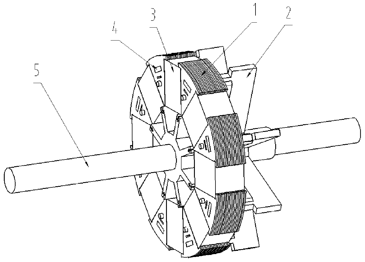
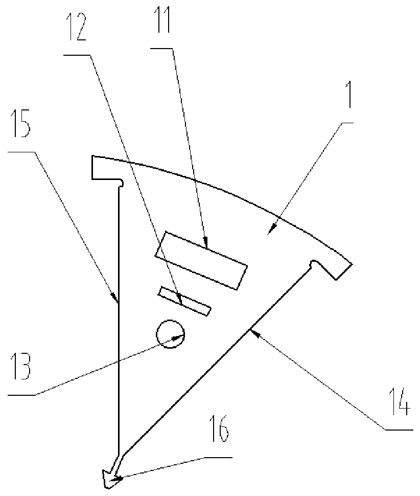
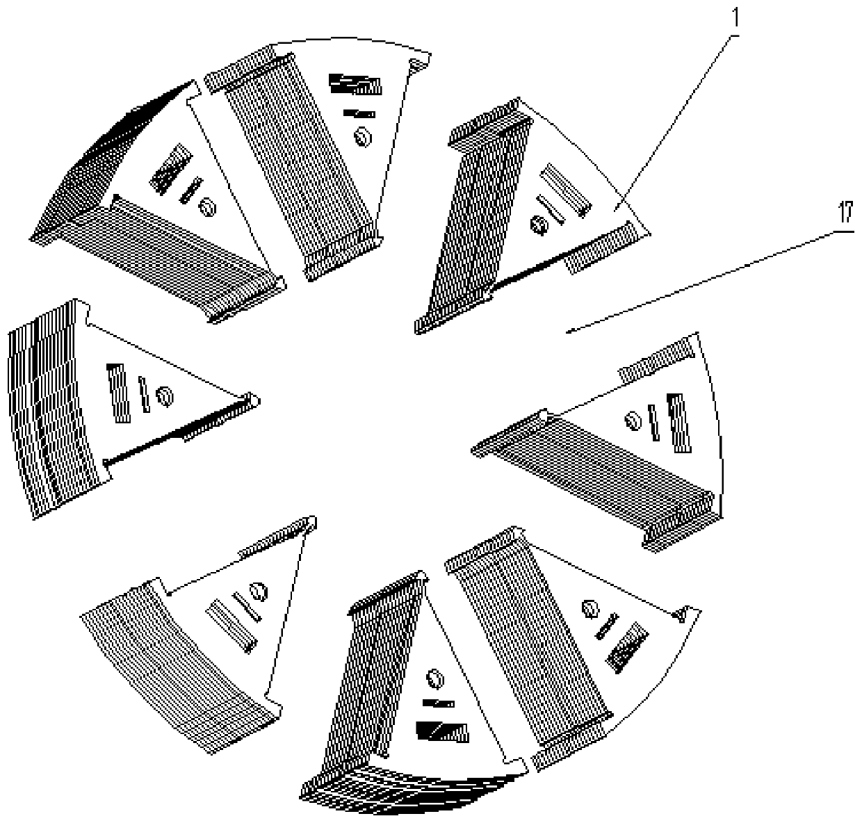
[0022] figure 1 What is shown is a structural schematic diagram of the present invention, which includes a rotor core 1 , a rotor core support 2 , a second permanent magnet group 3 , a first permanent magnet group 4 and a rotor shaft 5 . The rotor core 1 consists of figure 2 The rotor punches shown are stacked through riveting slots 12 . The rotor punch is provided with a first permanent magnet slot 11 , a positioning slot 13 , a riveting slot 12 and a reinforcing sheet 16 . The first permanent magnet slot 11, the positioning slot 13, the riveting slot 12 and the reinforcement piece 16 are radially distributed on the rotor punch; the rotor punch is laminated into the rotor core 1 by positioning the slot 13 and the riveting slot 12; The rotor core support 2 includes evenly distributed impellers 20 , and the impellers are provided with cyli...


PUM


Abstract

The invention discloses a permanent-magnet motor rotor core structure. The permanent-magnet motor rotor core structure comprises a rotor core, a rotor core support, a first permanent-magnet group, a second permanent-magnet group and a rotor shaft, wherein the rotor core is formed by laminating rotor punching sheets and comprises a first group of permanent-magnet grooves, a plurality of rotor coresand the rotor core support are combined and assembled to form a second group of permanent-magnet groove, the rotor core support is tightly connected with the rotor shaft, and the second permanent-magnet groove, the rotor core and the rotor core support form a centrifugal fan structure after the second permanent-magnet groove is assembled. By reliable installation of a permanent magnet of the permanent-magnet motor rotor core structure, a leakage magnetic phenomenon of the permanent magnet can be reduced, the iron core material and the magnetic material are saved, the cost of the whole motor is reduced, the permanent-magnet motor rotor core structure has high strength, the cooling effect of the motor is improved, and the internal temperature of the motor is reduced.

Description

technical field [0001] The invention relates to the technical field of permanent magnet motor core structure and rotor heat dissipation, in particular to a permanent magnet motor rotor core structure. Background technique [0002] In order to reduce the pollution emissions of urban vehicles and realize the development strategy of new energy vehicles, zero-emission electric buses have become the main force of new energy vehicles in cities. The drive system composed of motors as drive motors has very high cost performance and reliability. sex. Among them, permanent magnet motors are the main ones. [0003] The permanent magnet motor is excited by permanent magnets instead of coils, which not only saves a lot of copper and iron materials for making the motor, makes the whole machine smaller in size and lighter in weight, but also saves the power consumed by the excitation coil in operation, which is conducive to improving The electromechanical conversion efficiency of the mot...

Claims


Application Information

Patent Timeline
IPC IPC(8): H02K1/27H02K1/32H02K9/06
CPCH02K1/276H02K1/32H02K9/06
Inventor 钱喆王群京李国丽付冠东
Owner ANHUI UNIVERSITY
Learn More