Novel radio frequency electron accelerator structure

An electron accelerator and radio frequency technology, applied in the direction of electrical components, accelerators, etc., can solve the problems of difficult processing and assembly, complex structure, inconvenient use, etc., and achieve the effect of reducing processing difficulty and optimizing design

Pending Publication Date: 2019-09-06
成都奕康真空电子技术有限责任公司
View PDF1 Cites 3 Cited by
  • Summary
  • Abstract
  • Description
  • Claims
  • Application Information

AI Technical Summary

Problems solved by technology

[0005] 1. The existing focusing system is installed outside the accelerating tube and includes a water cooling system. The structure is complex and inconvenient to u

Method used


Image

  • Novel radio frequency electron accelerator structure
  • Novel radio frequency electron accelerator structure
  • Novel radio frequency electron accelerator structure

Examples


Embodiment

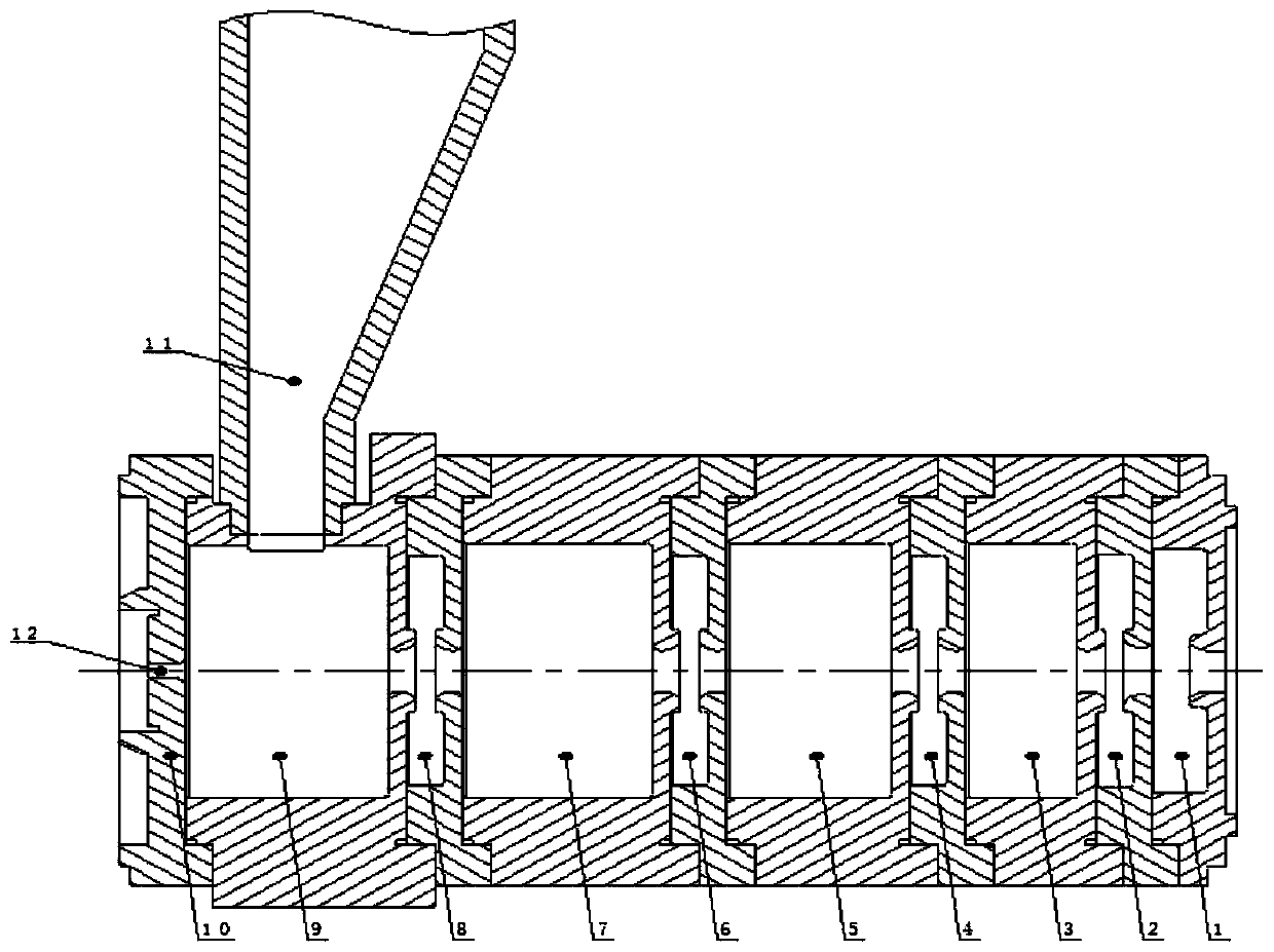
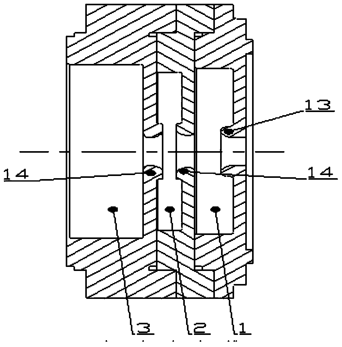
[0027] like Figure 1-3 Shown: This embodiment takes 5 accelerating cavities and 4 coupling cavities as an example for illustration, the actual number can be adjusted by those skilled in the art as needed. In this embodiment, the five accelerating chambers are respectively named as accelerating chamber A1, accelerating chamber A2, accelerating chamber A3, accelerating chamber A4, and accelerating chamber A5. The cavities are respectively named coupling cavity C1, coupling cavity C2, coupling cavity C3 and coupling cavity C4, and the numbers in the figure are 2, 4, 6, and 8, respectively.

[0028] Firstly, the accelerating chambers A1-A5 and the coupling chambers C1-C4 are assembled alternately, and then the sealing plate 10 is designed on the axial end surface of the accelerating chamber A5. Beam flow holes 12 are all designed on the axial end faces of the acceleration cavity, the coupling cavity and the sealing plate, and the center of the holes of these beam flow holes are ...


PUM


Abstract

The invention discloses a novel radio frequency electron accelerator structure comprising an accelerating cavity, a coupling cavity, a sealing plate and a feed-in waveguide; the accelerating cavity and the coupling cavity are alternately assembled together, the sealing plate is arranged on the axial end face of the accelerating cavity at the tail end, beam holes are designed in the axial end facesof the accelerating cavity, the coupling cavity and the sealing plate, the size of the beam hole in the sealing plate is smaller than that of other beam holes, and the feed-in waveguide communicatedwith the accelerating cavity is arranged on the radial side wall of the accelerating cavity at the tail end. According to the novel accelerator structure provided by the invention, an external focusing system is omitted, a coupling hole structure of the end surface of the cavity is omitted through an optimized design, and the processing difficulty is greatly reduced.

Description

technical field [0001] The invention belongs to the technical field of accelerators, and in particular relates to a radio frequency electron accelerator structure with simple structure and low processing difficulty. Background technique [0002] A small high-energy X-ray source is the basis of the entire high-energy industrial CT system. To generate high-energy X-rays with an energy exceeding 1 MeV, electrons must be accelerated by an electron linear accelerator, and the high-energy electron beam hits the target material to generate high-energy X-rays. In order to ensure the spatial resolution of CT imaging, there are strict requirements on the focal spot size of the electron beam. [0003] In the conventional design of the accelerator, a focusing system is added outside the accelerating tube, and a magnetic field is generated by electrifying the solenoid coil. For example, the patent number of an accelerating tube equipped with a focusing coil is CN201220722911.1. This te...

Claims


Application Information

Patent Timeline
IPC IPC(8): H05H7/22
CPCH05H7/22H05H2007/225
Inventor 刘咸生许晖周霖郭成伟
Owner 成都奕康真空电子技术有限责任公司
Why Eureka
Try Eureka