CT guidance-based lung puncture angle control device and angle control method thereof

A technology of puncture angle and control device, which is applied in puncture needles, inoculation and ovulation diagnosis, medical science, etc., can solve the problem of not thinking about purchasing, and achieve the effect of reducing repeated puncture rate, tissue trauma and complications

Inactive Publication Date: 2019-09-10
SHANGHAI PULMONARY HOSPITAL
View PDF8 Cites 3 Cited by
  • Summary
  • Abstract
  • Description
  • Claims
  • Application Information

AI Technical Summary

Problems solved by technology

The current navigation products are too expensive, and most primary hospitals will not consider buying them, so developing an economical, simple and practical angle control device will bring great convenience to the operation

Method used


Image

  • CT guidance-based lung puncture angle control device and angle control method thereof
  • CT guidance-based lung puncture angle control device and angle control method thereof
  • CT guidance-based lung puncture angle control device and angle control method thereof

Examples


Embodiment 1

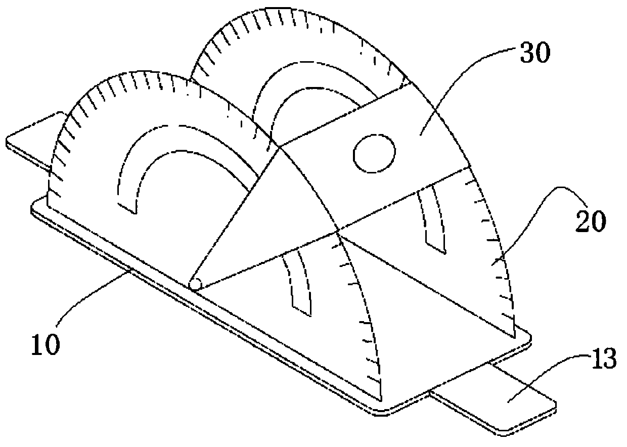
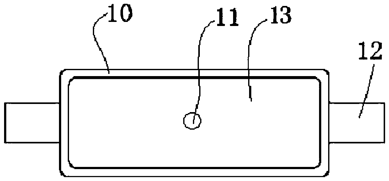
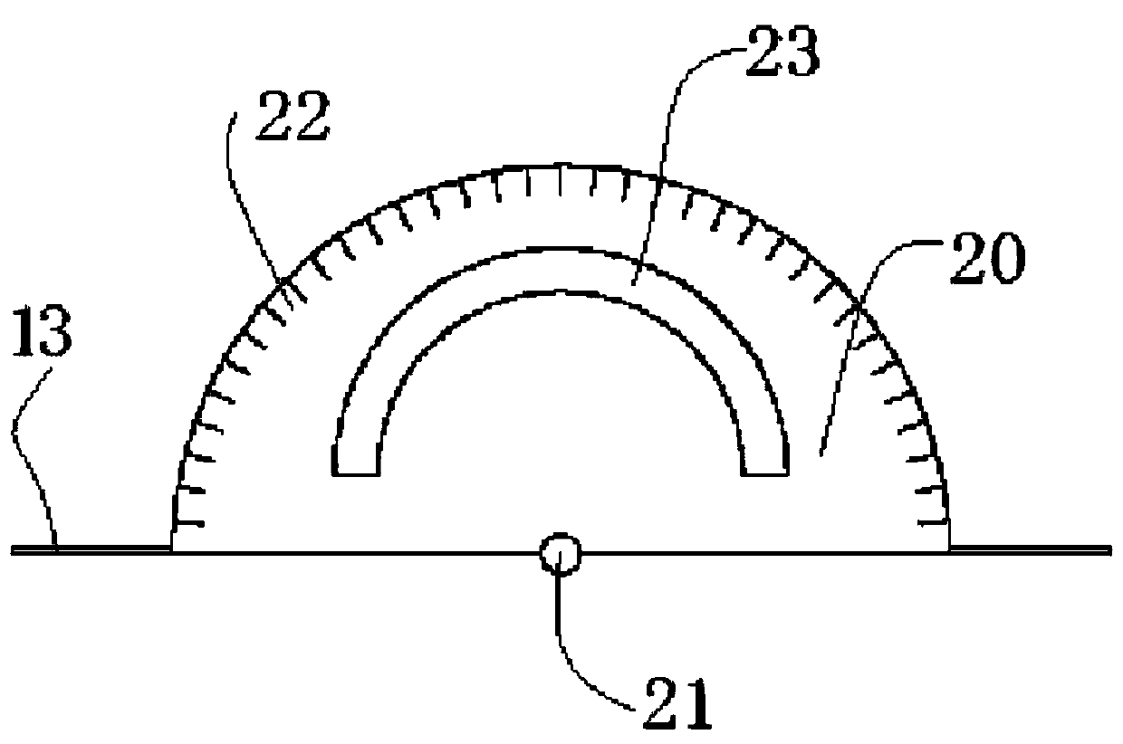
[0038] refer to Figure 1-4 As shown, a lung puncture angle control device based on CT guidance includes a base 10, an angle ring 20 and a needle insertion guide seat 30; wherein: the angle ring 20 is composed of two semicircular structural plates, and the two The structural plates are respectively symmetrically and detachably arranged on the left and right sides of the base 10, and the center of the structural plate is provided with a hinge hole 21, and the edge position is provided with a scale 22; the needle insertion guide seat 30 is Inverted U-shaped structure, the top of which is provided with a needle entry hole 31, and the bottom ends of the two legs 32 are hingedly arranged in the scale 22; wherein, the top of the needle entry guide seat 30 is hingedly arranged in the hinge hole 21 The center of the inner leg 32 is rotated to a certain angle along the circumferential direction of the angle ring 20 , and the puncture needle passes through the needle entry hole 31 and e...

Embodiment 2

[0046] Using the lung puncture based on CT guidance as described in Example 1, a method for controlling the lung puncture angle based on CT guidance to assist doctors in local treatment of lung lesions is provided, specifically including the following steps:

[0047] Step 1. Under the premise of the patient's comfort and stability, select the corresponding supine, prone, oblique and other positions based on the principle of the shortest distance between the lesion and the body surface;

[0048] Step 2, stick a fence locator on the lesion area, and perform a positioning scan; take the maximum diameter of the lesion and avoid bones, blood vessels, and necrotic areas of the lesion;

[0049] Step 3: After the needle entry point is selected, mark it on the skin, and at the same time use the CT portable software to calculate the puncture depth.

[0050] Step 4, after local skin disinfection and covering the drape, infiltration anesthesia, remove the drape; fix the groove 13 of the b...


PUM


Abstract

The invention discloses a CT guidance-based lung puncture angle control device and an angle control method thereof. The angle control device comprises a base, an angle ring and an needle inlet guide seat; the angle ring consists of two semi-circular structural plates, the two structural plates are symmetrically disposed on the left and right sides of the base respectively, hinge holes are formed in the circular centers of the structural plates, and the edges of the structural plates are provided with scales; the needle inlet guide seat is of an inverted U-shaped structure, a needle inlet holeis formed in the top of the needle inlet guide seat, and the bottoms of two support legs of the needle inlet guide seat are hinged into the scales, wherein the top of the needle inlet guide seat is rotated to a certain angle in the circumferential direction with the support legs hinged into the hinge holes as the circular centers and then penetrates out of a needle outlet hole in the middle of thebase after a puncture needle penetrates into the needle inlet hole. The angle control device and the method can effectively control the needle inlet angle and control the error within 0.5 cm, so thatthe puncture is carried out successfully at a time, the repeated puncture rate is decreased, and tissue trauma and complications brought by puncture are reduced.

Description

technical field [0001] The invention relates to the technical field of medical auxiliary equipment, in particular to a CT-guided lung puncture angle control device and an angle control method thereof. Background technique [0002] CT-guided percutaneous lung puncture has been recognized by the majority of medical workers due to its minimal trauma, ease of use, and is generally considered to be relatively safe and reliable. This technique can provide samples for histocytological examination of the disease, and can also be used for local treatment of lesions. The accuracy and complications of puncture have been the two major subjects of clinical research. After the optimal needle insertion point is selected, the accuracy of puncture is determined by three factors: needle insertion point, needle insertion depth and angle. Only when the needle entry point, puncture angle and lesion depth are correctly and meticulously selected, can the one-time success of puncture be guarantee...

Claims


Application Information

Patent Timeline
IPC IPC(8): A61B10/02A61B17/34A61B34/10
CPCA61B17/3403A61B10/0233A61B34/10A61B2017/3407A61B2034/108
Inventor 陈昶孙维言汪洋邓家骏佘云浪
Owner SHANGHAI PULMONARY HOSPITAL
Why Eureka
Try Eureka