Novel engraving drill bit utilizing wall attaching function of air flow

A technology of wall attachment and drill bits, which is applied in the field of manufacturing, can solve problems such as physical damage, damage to the health of workers, and dust pollution, and achieve the effects of reducing friction, protecting health, and reducing dust floating

Active Publication Date: 2019-09-10
湖北广茂石材有限公司
View PDF7 Cites 0 Cited by
  • Summary
  • Abstract
  • Description
  • Claims
  • Application Information

AI Technical Summary

Problems solved by technology

[0003] However, during the carving process of stone carving, a lot of dust will be generated when the drill bit contacts the stone. In the existing technology, most of the drill bits have a single structure and can only be carved. There is no device that can absorb dust on the drill bit, but , the human body inhales too much dust, which will cause damage to the body. Therefore, the sculptor usually wears a mask to reduce the inhalation of the generated dust into the body, although this method will reduce the dust to a certain extent. However, if the mask is used for a long time, the dust will breed bacteria through the water vapor discharged on the mask by the human body. When the human body inhales, these bacteria will enter the body of the staff. It serves the purpose of protecting the health of the staff, but also imperceptibly damages the health of the staff, and after long-term use of the mask, it will be polluted by dust and needs to be cleaned by the staff, which increases the labor of the staff and is inconvenient to use , therefore, a new type of engraving drill is needed to solve this problem

Method used


Image

  • Novel engraving drill bit utilizing wall attaching function of air flow
  • Novel engraving drill bit utilizing wall attaching function of air flow
  • Novel engraving drill bit utilizing wall attaching function of air flow

Examples


Embodiment Construction

[0020] The following will clearly and completely describe the technical solutions in the embodiments of the present invention with reference to the accompanying drawings in the embodiments of the present invention. Obviously, the described embodiments are only some, not all, embodiments of the present invention. Based on the embodiments of the present invention, all other embodiments obtained by persons of ordinary skill in the art without making creative efforts belong to the protection scope of the present invention.

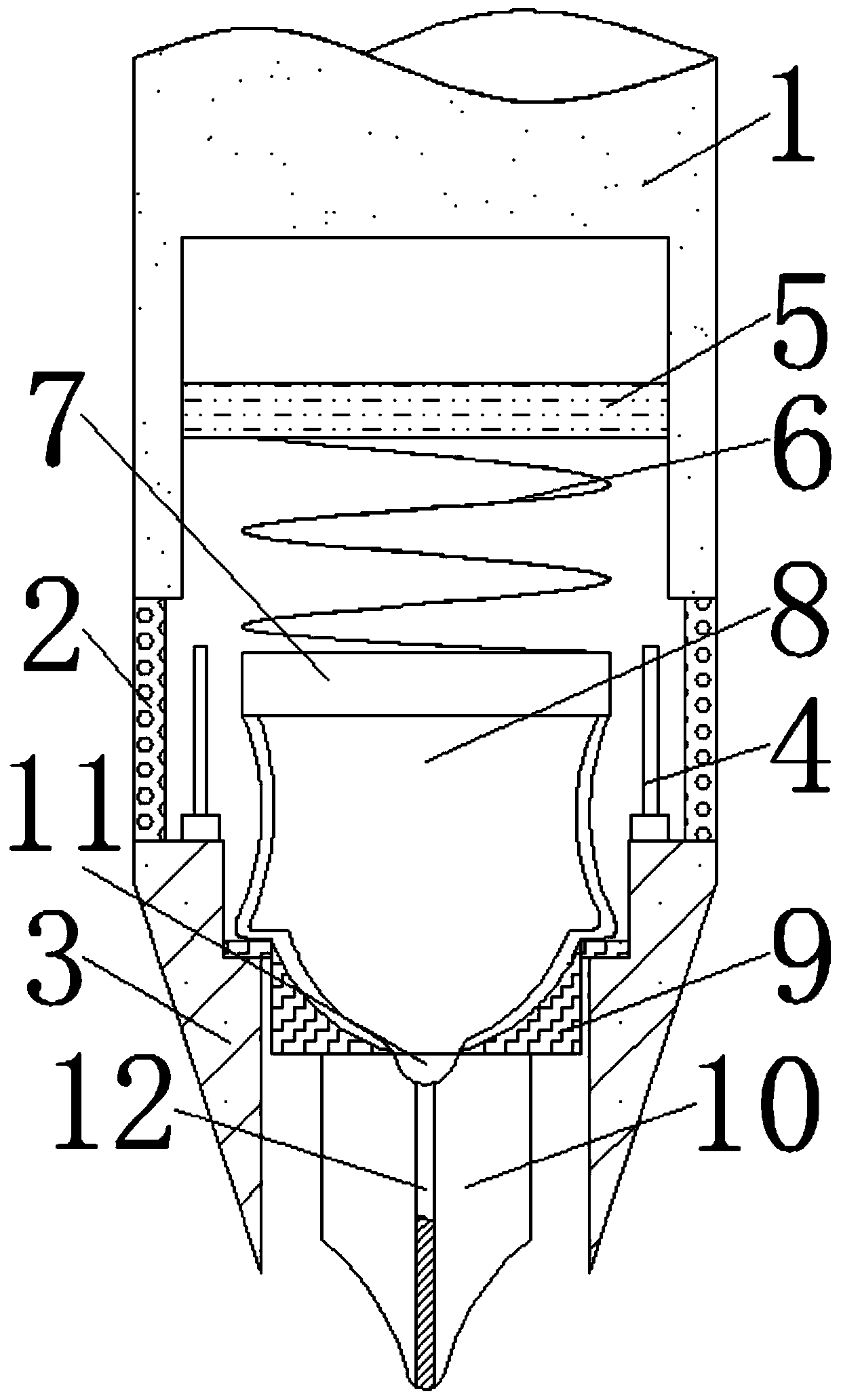
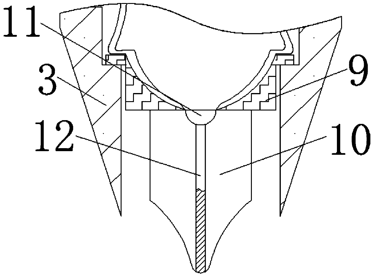
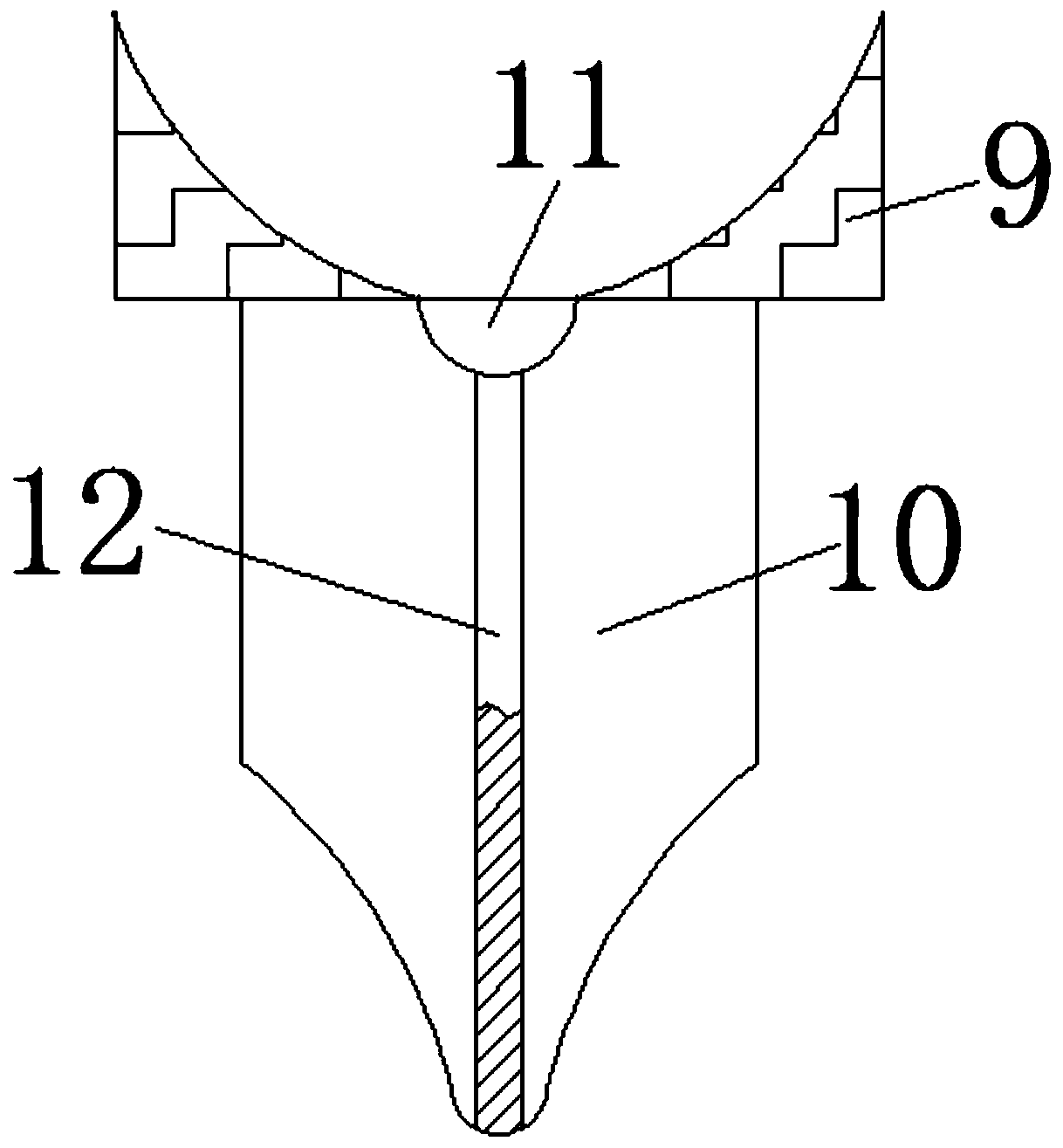
[0021] see Figure 1-3 , a new type of engraving drill using the effect of airflow wall attachment, including a drill rod 1, the lower end of the drill rod 1 is movably installed with two symmetrical partitions 2, the partitions 2 are made of metal wires, mainly to allow the air to The dust in the dust is absorbed by the dust collection strip 4. Two symmetrical fixed rings 3 are installed on the lower end of the partition net 2. The upper end of the fixed ring...


PUM


Abstract

Disclosed is a novel engraving drill bit utilizing the wall attaching function of air flow. The novel engraving drill bit comprises a drill rod. Two symmetric separation nets are movably arranged at the lower end of the drill rod. Two symmetrical fixing rings are movably arranged at the lower ends of the separation nets. The upper ends of the fixing rings are in threaded connection with integratedstrips. A fixed plate is fixedly arranged in the drill rod. The lower surface of the fixed plate is elastically connected with a fixing block through a pressure spring. The lower surface of the fixing block is in threaded connection with a plastic pipe. The drill rod, the separation nets, the fixing rings, a dust collecting strip, the fixed plate and a drill bit body are cooperatively used, so that the wall attaching function of the air flow can be effectively used for adsorbing and collecting dust, it is guaranteed that during engraving, the dust does not continue to float upwards and is notsucked into bodies of workers, the body health of the workers is protected, and the possibility that dust generated by engraving is absorbed by human bodies and does harm to the human bodies is reduced.

Description

technical field [0001] The invention relates to the field of manufacturing technology, in particular to a novel engraving drill utilizing the airflow attachment effect. Background technique [0002] The engraving machine is an important engraving tool for stonemasons and other workers. It can carve out the desired shape for wood, stone, jade, metal objects, etc., and create a visual and tactile artistic image with a certain space to reflect society. Life, art that expresses the artist's aesthetic feelings, aesthetic emotions, and aesthetic ideals At present, due to people's pursuit of life and aesthetics, stone carvings have become important ornaments. [0003] However, during the carving process of stone carving, a lot of dust will be generated when the drill bit contacts the stone. In the existing technology, most of the drill bits have a single structure and can only be carved. There is no device that can absorb dust on the drill bit, but , the human body inhales too muc...

Claims


Application Information

Patent Timeline
Patent Type & Authority Applications(China)
IPC IPC(8): B44B1/06B44B3/06B23B51/00
CPCB23B51/00B44B1/06B44B3/061
Inventor 徐成甘瑛张乐
Owner 湖北广茂石材有限公司
Why Eureka
Try Eureka