
A planetary gear driven wave energy power generation device

A power generation device and wave energy technology, which is applied to gear transmission devices, transmission devices, electromechanical devices, etc., can solve problems such as increased energy transmission loss, complicated internal gear trains, and difficult maintenance, so as to reduce mechanism loss and increase energy. The effect of collection efficiency and anti-wind and wave ability, and compact structure of the device

Active Publication Date: 2020-05-19
HUAZHONG UNIV OF SCI & TECH
View PDF9 Cites 2 Cited by
  • Summary
  • Abstract
  • Description
  • Claims
  • Application Information

AI Technical Summary

Problems solved by technology

The device adopts a mechanical transmission mechanism, which can absorb unstable wave energy and convert it into electrical energy. However, the internal gear train of the device is complicated and the structure is not compact enough. Too many gears in various mechanisms cause energy transmission loss to increase, and maintenance is difficult.
[0007] From the above analysis, it can be seen that in the field of wave power generation, although there are various schemes using different principles and using different mechanisms, these schemes still have room for improvement in terms of improving energy collection and conversion efficiency, simplifying structures and enhancing reliability.

Method used


Image

  • A planetary gear driven wave energy power generation device
  • A planetary gear driven wave energy power generation device
  • A planetary gear driven wave energy power generation device

Examples


Embodiment Construction

[0028] In order to make the object, technical solution and advantages of the present invention clearer, the present invention will be further described in detail below in conjunction with the accompanying drawings and embodiments. It should be understood that the specific embodiments described here are only used to explain the present invention, not to limit the present invention. In addition, the technical features involved in the various embodiments of the present invention described below can be combined with each other as long as they do not constitute a conflict with each other.

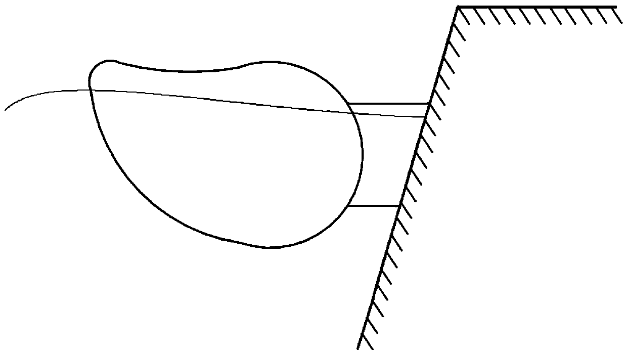
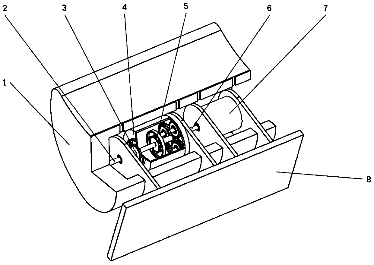
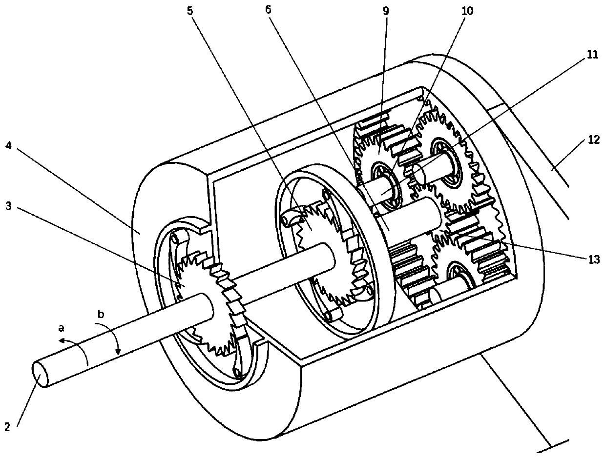
[0029] Such as figure 2 As shown, the embodiment of the present invention provides a planetary gear drive wave energy generating device, which includes a wave energy generating unit, a floating body 1 and a body support 8, wherein the wave energy generating unit is installed inside the floating body 1, and passes through The support cantilever 12 is connected with the body support 8; the wave ...


PUM


Abstract

The invention belongs to the field of wave power generation and particularly discloses a wave power generation device adopting planet gear transmission. The wave power generation device adopting planet gear transmission comprises a wave power generation unit, a floating body and a body support. The wave power generation unit is installed inside the floating body and connected with the body supportthrough a support cantilever. The wave power generation unit comprises a reversing assembly and a power generator. The reversing assembly comprises a tooth ring roller, a roller ratchet wheel clutch,a main shaft ratchet wheel clutch and a planet gear train. The roller ratchet wheel clutch, the main shaft ratchet wheel clutch and the planet gear train are sequentially arranged in the tooth ring roller, by means of cooperative action of the tooth ring roller, the roller ratchet wheel clutch, the main shaft ratchet wheel clutch and the planet gear train, the reversing assembly changes reciprocating rotational movement in two directions into unidirectional continuous rotation and drives a power generator to generate electricity. The wave power generation device adopting planet gear transmission is simple and compact in structure and high in reliability and improves energy utilization ratio. When the wave power generation device adopting planet gear transmission is arranged offshore, multiple power generation devices are installed on a herringbone frame, a linear execution mechanism and direction fins are installed on the frame, and energy collection demands under different conditionscan be met.

Description

technical field [0001] The invention belongs to the field of wave energy power generation, and more particularly relates to a planetary gear driven wave energy power generation device. Background technique [0002] In recent years, with the continuous consumption of non-renewable energy such as oil and natural gas, people have turned their attention to the development of renewable energy such as wind energy and ocean energy. Can belong to the ranks of new energy sources to be developed and utilized. Ocean energy is contained in ocean currents and waves, and wave energy is almost everywhere. Converting wave energy into electrical energy is a very valuable research direction. [0003] At present, the development and utilization of wave energy is still in the experimental research stage, and various experimental power generation devices have been developed in some coastal areas. Further analysis of the published patents in the field of wave power generation shows that althoug...

Claims


Application Information

Patent Timeline
Patent Type & Authority Patents(China)
IPC IPC(8): F03B13/18F03B13/20F16H1/32F16H33/08H02K7/02H02K7/116
CPCF03B13/1815F03B13/20F16H1/321F16H33/08F16H2001/327F16H2001/328H02K7/025H02K7/116F05B2260/40311F05B2260/40312Y02E10/30
Inventor 杨少龙孙延浩潘新祥向先波向阳陈松豪
Owner HUAZHONG UNIV OF SCI & TECH
Learn More