LNG self-pressurization storage tank

A self-pressurization and storage tank technology, which is applied in the direction of fixed-capacity gas storage tanks, pressure vessels, and non-pressure vessels, can solve the problems of large pressure fluctuations in storage tanks, large pressure fluctuations, and inability to accurately control pressure and flow. , to achieve the effect of simple structure and easy operation

Inactive Publication Date: 2019-09-10
JIANGSU UNIV OF SCI & TECH +1
View PDF9 Cites 5 Cited by
  • Summary
  • Abstract
  • Description
  • Claims
  • Application Information

AI Technical Summary

Problems solved by technology

[0003] The self-pressurization system of the liquid storage tank in the prior art only controls the liquid intake and self-pressurization action through the switch of the manual valve, the pressure in the storage tank fluctuates greatly, and the pressure and flow cannot be accurately controlled
CN201720938193.4 discloses a rapid self-pressurization pipeline for low-temperature storage tanks, which realizes self-pressurization through the upper anti-gas sealing pipe, liquid phase shut-off valve, gasification supercharger, booster

Method used


Image

  • LNG self-pressurization storage tank
  • LNG self-pressurization storage tank

Examples


Embodiment Construction

[0017] The present invention will be described in further detail below in conjunction with the accompanying drawings.

[0018] In order to make the object, technical solution and advantages of the present invention clearer, the present invention will be further described in detail below in conjunction with the accompanying drawings and specific embodiments. The following examples can enable those skilled in the art to understand the present invention more comprehensively, but the present invention is not limited to the scope of the described examples.

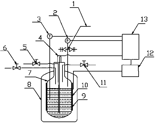
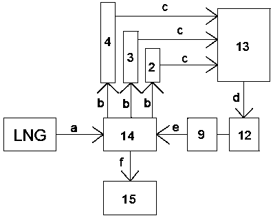
[0019] Such as figure 1 As shown, the specific embodiment adopts the following technical scheme: it includes a liquid storage tank body 14 and an auxiliary thermal pressurization device; Composition, the valve pipeline is arranged on the top of the liquid storage tank body 14, including the double safety valve 1, the liquid inlet and outlet valve 5, the gas valve 6 and the vent valve 11, because the pressure of the cryogenic l...


PUM


Abstract

The invention discloses an LNG self-pressurization storage tank, and relates to the technical field of self-pressurization liquid supply storage tanks for laboratories. A liquid storage tank body of the LNG self-pressurization storage tank is composed of a stainless steel inner container, a stainless steel outer shell, a vacuum insulation interlayer and a valve pipeline, the valve pipeline is arranged at the top of the liquid storage tank body, a pressure sensor, a temperature sensor and a liquid level sensor in an auxiliary thermal pressurization device are arranged at the top of the liquid storage tank body, the pressure sensor, the temperature sensor, the liquid level sensor and a power supply are electrically connected with a control unit correspondingly, a thermal resistor is arrangedon the outer surface of the stainless steel inner container, the outer surface of the thermal resistor is covered with an isolation and heat insulation covering layer, and the thermal resistor is electrically connected with the power supply and the control unit. The LNG self-pressurization storage tank has the advantages that the vaporization degree of LNG in the tank is controlled through the size of the power of the thermal resistor so that the pressure, the liquid level, the temperature and other physical states in the tank can be relatively accurately controlled, the operation is simplerand more convenient, the heat loss of the thermal resistor can be reduced through the isolation and heat insulation covering layer, and the waste is reduced.

Description

technical field [0001] The invention relates to the technical field of laboratory self-pressurized liquid supply storage tanks, in particular to an LNG self-pressurized storage tank. Background technique [0002] The initial liquefied natural gas filled into the liquid storage tank is generally under normal pressure. When using it, the storage tank needs to be self-pressurized first. When the pressure increases to the required pressure range for liquid discharge, the liquid discharge will start. air supply. The basic principle of self-pressurization is to discharge the low-temperature liquid in the storage tank, vaporize it through the vaporizer, and then return to the gas phase space of the self-storage tank. Since the specific volume of the gas is much larger than that of the liquid, the gas can be used to squeeze the LNG in the storage tank to achieve the purpose of pressurizing the storage tank. [0003] The self-pressurization system of the liquid storage tank in the ...

Claims


Application Information

Patent Timeline
IPC IPC(8): F17C3/04F17C7/02F17C7/04F17C13/02F17C13/04
CPCF17C3/04F17C7/02F17C13/02F17C13/025F17C13/026F17C13/04F17C2205/0332F17C2221/033F17C2223/0161F17C2225/0161F17C2227/0304
Inventor 肖民单航
Owner JIANGSU UNIV OF SCI & TECH
Why Eureka
Try Eureka