A high-efficiency energy-saving boiler

A high-efficiency energy-saving boiler technology, which is applied to steam boilers, steam boiler accessories, steam boiler components, etc., can solve the problems of high exhaust gas flow rate, waste, energy waste, etc., and achieve the effect of avoiding emissions

Active Publication Date: 2020-11-10
荣盛成(北京)工业技术有限公司
View PDF7 Cites 0 Cited by
  • Summary
  • Abstract
  • Description
  • Claims
  • Application Information

AI Technical Summary

Problems solved by technology

At present, more mature and advanced boilers are usually composed of a pot shell and a furnace, and the water is heated through the furnace, but in fact, when the fuel in the boiler is burned, a lot of heat will be discharged outside through the exhaust gas at the same time, resulting in a lot of energy wasted;
[0003] There are some energy-saving boilers in the prior art, which directly introduce the exhaust gas generated by combustion into the water pipeline, so that the heat in the exhaust gas can be transferred to the water, but the main problem of this solution is that the flow rate of the exhaust gas is often too high, and it cannot be heated in the pipeline. It stays for a long time, so that the heat in the exhaust gas cannot be effectively transferred to the water, resulting in a large amount of waste

Method used


Image

  • A high-efficiency energy-saving boiler
  • A high-efficiency energy-saving boiler
  • A high-efficiency energy-saving boiler

Examples


Embodiment

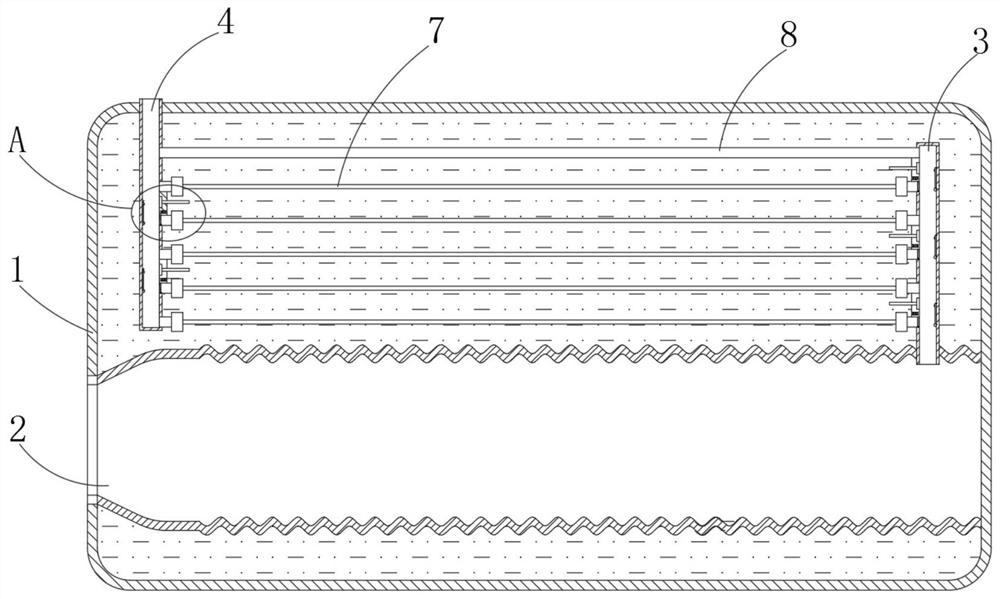
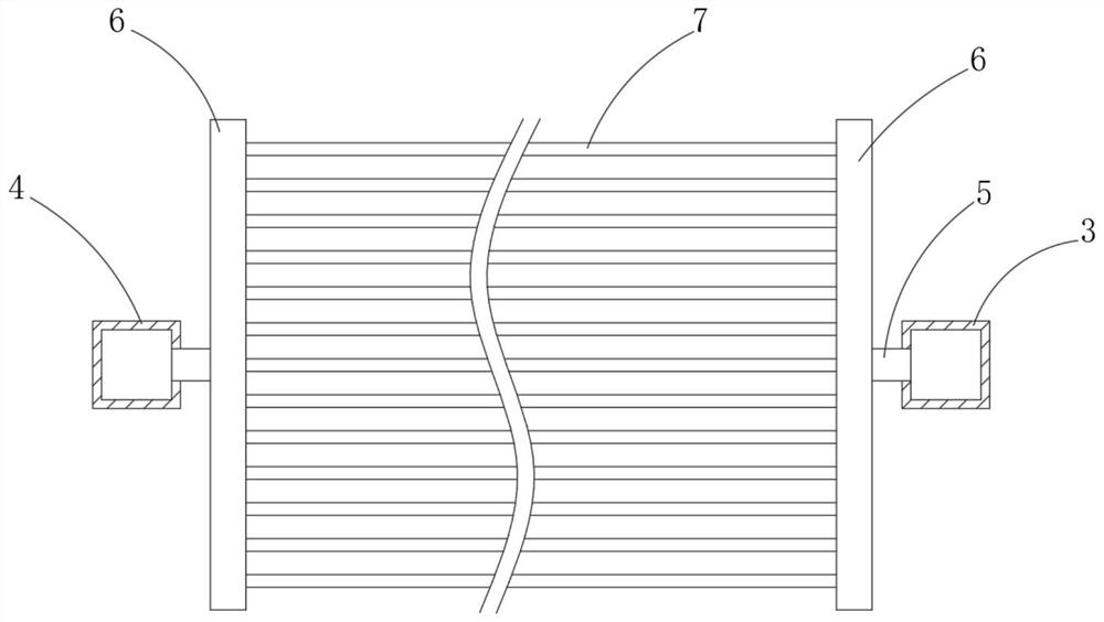
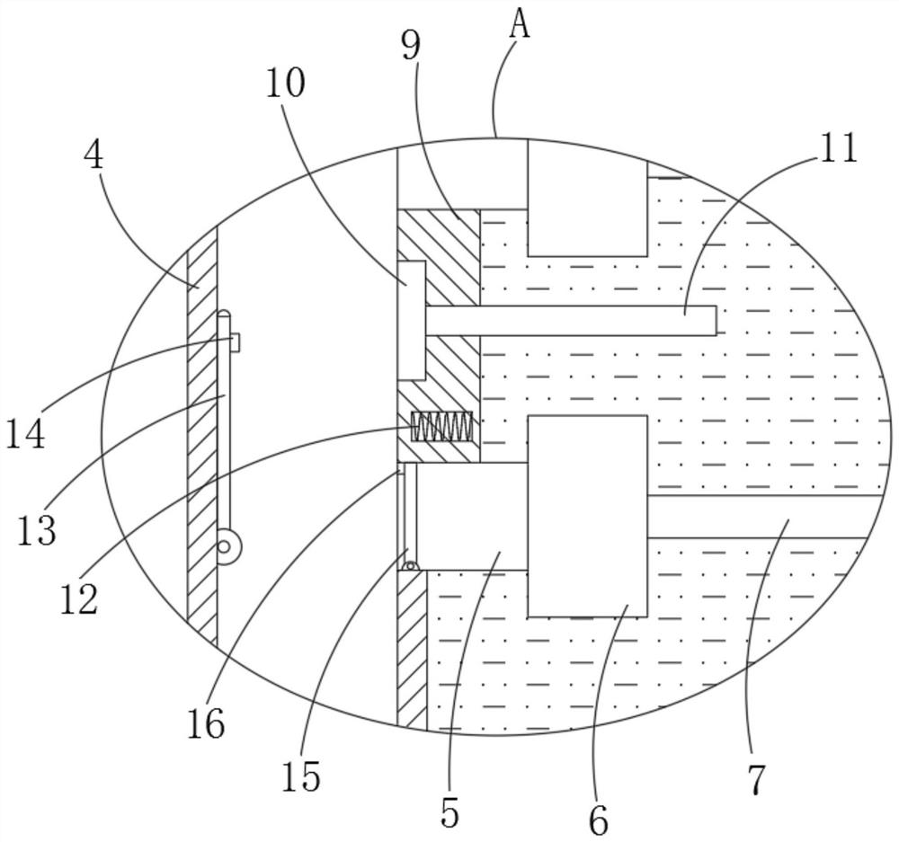
[0023] refer to Figure 1-3 , a high-efficiency energy-saving boiler, including a boiler body 1 and a furnace 2, the boiler body 1 is provided with a first vertical pipe 3 and a second vertical pipe 4, the lower end of the first vertical pipe 3 communicates with the furnace 2, the first vertical pipe The upper end of the pipe 3 is closed, the second vertical pipe 4 penetrates upwards through the outer wall of the boiler body 1, the lower end of the second vertical pipe 4 is closed, and the ends of the first vertical pipe 3 and the second vertical pipe 4 are fixed and communicated with a short Tube 5, each short tube 5 is fixedly connected with a shunt pipe 6, two shunt pipes 6 at the same height communicate with a plurality of metal heat-conducting pipes 7, the first vertical pipe 3 and the second vertical pipe 4 are connected with the The junction of the short tube 5 is provided with a plurality of automatic control devices, and the automatic control devices are alternately a...

Embodiment 2

[0034]The difference between this embodiment and Embodiment 1 is that the part of the second vertical pipe 4 located outside the boiler body 1 is sealed and connected with a horizontally arranged outer pipe 17. The cross section of the outer pipe 17 is a square structure, and the upper wall of the outer pipe 17 is fixed. A baffle 18 is connected, and a third rotating plate 19 is connected to the baffle 18 for damping rotation. The outer tube 17 is connected with a return pipe 20 .

[0035] It is difficult to ensure the complete combustion of fuel during the combustion process of the boiler, so that the air flowing out of the second standpipe 4 contains a certain amount of combustibles such as carbon monoxide, and at the same time, there are non-combustible gases such as carbon monoxide whose molecular weight is smaller than that of carbon dioxide and sulfur dioxide, so that carbon monoxide There is a tendency to move upwards, so when the air flowing out of the second vertical p...


PUM


Abstract

The invention discloses an efficient energy-saving boiler. A boiler body and a boiler container are included. The boiler body is internally provided with a first vertical pipe and a second vertical pipe. The lower end of the first vertical pipe communicates with the boiler container. The upper end of the first vertical pipe is closed. The second vertical pipe upwards penetrates through the outer wall of the boiler body. The lower end of the second vertical pipe is closed. Each of the ends, getting close to each other, of the first vertical pipe and the second vertical pipe fixedly communicateswith one short pipe. The efficient energy-saving boiler has the advantages that multiple heat conduction pipes are arranged in the efficient energy-saving boiler, an automatic control device controlshot air in the boiler to flow into the heat conduction pipes from the positions of short pipes at different positions, it is ensured that the obvious temperature difference exists between the hot airof the heat conduction pipes and the water at the position, hot air generated due to boiler combustion can stay in the heat conduction pipes at the obvious temperature difference position for a longtime, heat in the hot air can be sufficiently conducted into water, and energy of energy heating in the boiler is utilized to the maximum.

Description

technical field [0001] The invention relates to the technical field of boilers, in particular to a high-efficiency and energy-saving boiler. Background technique [0002] As a heat source equipment widely used in production and life, the boiler is widely promoted due to its unique performance, which heats water through the furnace and pipe walls, and the water is heated to generate steam. At present, more mature and advanced boilers are usually composed of a pot shell and a furnace, and the water is heated through the furnace, but in fact, when the fuel in the boiler is burned, a lot of heat will be discharged outside through the exhaust gas at the same time, resulting in a lot of energy wasted; [0003] There are some energy-saving boilers in the prior art, which directly introduce the exhaust gas generated by combustion into the water pipeline, so that the heat in the exhaust gas can be transferred to the water, but the main problem of this solution is that the flow rate ...

Claims


Application Information

Patent Timeline
Patent Type & Authority Patents(China)
IPC IPC(8): F24H9/00F22B37/00F23B80/02F23C9/06
CPCF22B37/00F23B80/02F23C9/06F24H9/0005
Inventor 顾海明
Owner 荣盛成(北京)工业技术有限公司
Why Eureka
Try Eureka