Eureka AIR delivers breakthrough ideas for toughest innovation challenges, trusted by R&D personnel around the world.

High-frequency transformer

A high-frequency transformer and oil tank technology, applied in the field of transformers, can solve problems such as poor cooling effect and limited application scope.

Active Publication Date: 2020-06-19
遂川东辰电子科技有限公司
View PDF9 Cites 0 Cited by
  • Summary
  • Abstract
  • Description
  • Claims
  • Application Information

AI Technical Summary

Problems solved by technology

The high-frequency transformer with this structure, including the oil tank and the oil circulation cooling system, can automatically transport the cooling oil in the oil tank to the oil cooling system through the oil pump for cooling and cooling, but the cooling effect of the oil circulation cooling system of this high-frequency transformer is not good. , which limits its scope of application

Method used


Image

  • High-frequency transformer
  • High-frequency transformer
  • High-frequency transformer

Examples


Embodiment Construction

[0022] The standard parts used in the present invention can be purchased from the market, and the special-shaped parts can be customized according to the instructions and the accompanying drawings. The specific connection methods of each part adopt mature bolts, rivets, welding in the prior art , pasting and other conventional means, no longer described in detail here.

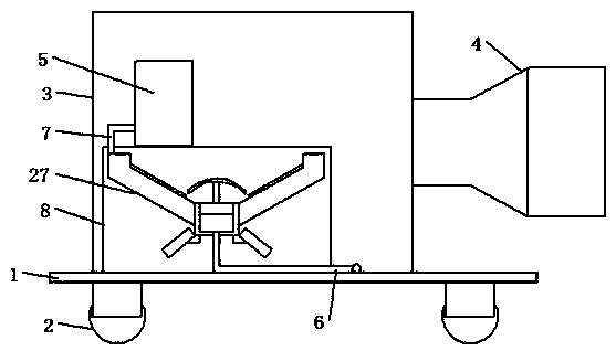
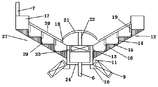
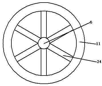
[0023] refer to Figure 1-7 A specific embodiment of the present invention includes a fuel tank 3 and an oil pump 5 connected through the fuel tank 3. The oil pump 5 is connected with a heat dissipation part 27 through an oil inlet pipe 7. The heat dissipation part 27 is connected with the fuel tank 3 through an oil discharge pipe 6 to dissipate heat. Part 27 comprises annular pipe 17, and the bottom of annular pipe 17 is connected with stepped portion 12, and stepped portion 12 comprises several annular plates 15 and cylinder 14 arranged from bottom to top, annular plate 15 and cylinder 14 are interconnected,...


PUM


Abstract

The invention discloses a high-frequency transformer. The high-frequency transformer comprises an oil tank, an oil pump, a heat dissipation part, an oil drain pipe and an oil inlet pipe, the heat dissipation part comprises an annular pipe, a step part is connected below the annular pipe, the step part comprises a plurality of annular plates and cylinders which are arranged from bottom to top, theannular plates are connected with the cylinders, the annular plates and the cylinders gradually increase in radius from bottom to top, spiral grooves which are spirally arranged are formed in the upper portion of the annular plate, a first cooling fin is connected below each annular plate, a hollow ring sleeve is connected to the inner side below the step part, a plurality of annularly arranged first through holes are formed in the outer side of the hollow ring sleeve, the first through hole is located in the inner side of the step part, the inner side of the bottom of the hollow ring sleeve is connected with a plurality of guide pipes in a penetrating mode, the inner sides of the guide pipes are communicated with the oil discharging pipe, the bottom of the hollow ring sleeve is further connected with a fixing ring, and the outer side of the fixing ring is connected with a plurality of annularly-arranged first fans. Defects in the prior art can be overcome, and the high-frequency transformer has a better heat dissipation effect.

Description

technical field [0001] The invention relates to a transformer, especially a high-frequency transformer. Background technique [0002] High-frequency transformer is a power transformer whose operating frequency exceeds intermediate frequency (10kHz). It is mainly used as a high-frequency switching power transformer in high-frequency switching power supplies, and is also used as a high-frequency inverter in high-frequency inverter power supplies and high-frequency inverter welding machines. power transformer. According to the working frequency, it can be divided into several grades: 10kHz-50kHz, 50kHz-100kHz, 100kHz-500kHz, 500kHz-1MHz, and above 10MHz. The high-frequency transformer is the most important component of the switching power supply. Chinese utility model patent CN 202018870 U discloses a new type of high frequency transformer. The high-frequency transformer with this structure, including the oil tank and the oil circulation cooling system, can automatically tran...

Claims


Application Information

Patent Timeline
Patent Type & Authority Applications(China)
IPC IPC(8): H01F27/08H01F27/12H01F27/22
CPCH01F27/08H01F27/12H01F27/22
Inventor 汪强
Owner 遂川东辰电子科技有限公司
Why Eureka
Eureka Blog
Learn More