Pulse modulation circuit and method for triggering thyristor

A technology of pulse modulation circuit and pulse width modulation, which is applied in the direction of pulse technology, electronic switches, electrical components, etc. It can solve the problems of motor out of control, circuit heating, and bridge circuit conduction at the same time, so as to improve quality and reduce pulse action time , the effect of improving reliability

Active Publication Date: 2019-08-30
GREE ELECTRIC APPLIANCES INC +1
View PDF9 Cites 0 Cited by
  • Summary
  • Abstract
  • Description
  • Claims
  • Application Information

AI Technical Summary

Problems solved by technology

[0003] However, the above-mentioned driving method has high requirements on the performance of the thyristor driver chip itself. Since the driver chip is triggered at full duty within one trigger cycle, the current flowing through the driver chip is large, and the circuit may generate heat or even be damaged during long-term operation. problems, and then produce many adverse consequences such as motor runaway, upper bridge and lower bridge of the bridge circuit being turned on at the same time, which cannot meet the driving requirements of the circuit

Method used


Image

  • Pulse modulation circuit and method for triggering thyristor
  • Pulse modulation circuit and method for triggering thyristor
  • Pulse modulation circuit and method for triggering thyristor

Examples


Embodiment Construction

[0025] In order to make the above objects, features and advantages of the present invention more comprehensible, specific implementations of the present invention will be described in detail below in conjunction with the accompanying drawings. In the following description, numerous specific details are set forth in order to provide a thorough understanding of the present invention. However, the present invention can be implemented in many other ways different from those described here, and those skilled in the art can make similar improvements without departing from the connotation of the present invention, so the present invention is not limited by the specific embodiments disclosed below.

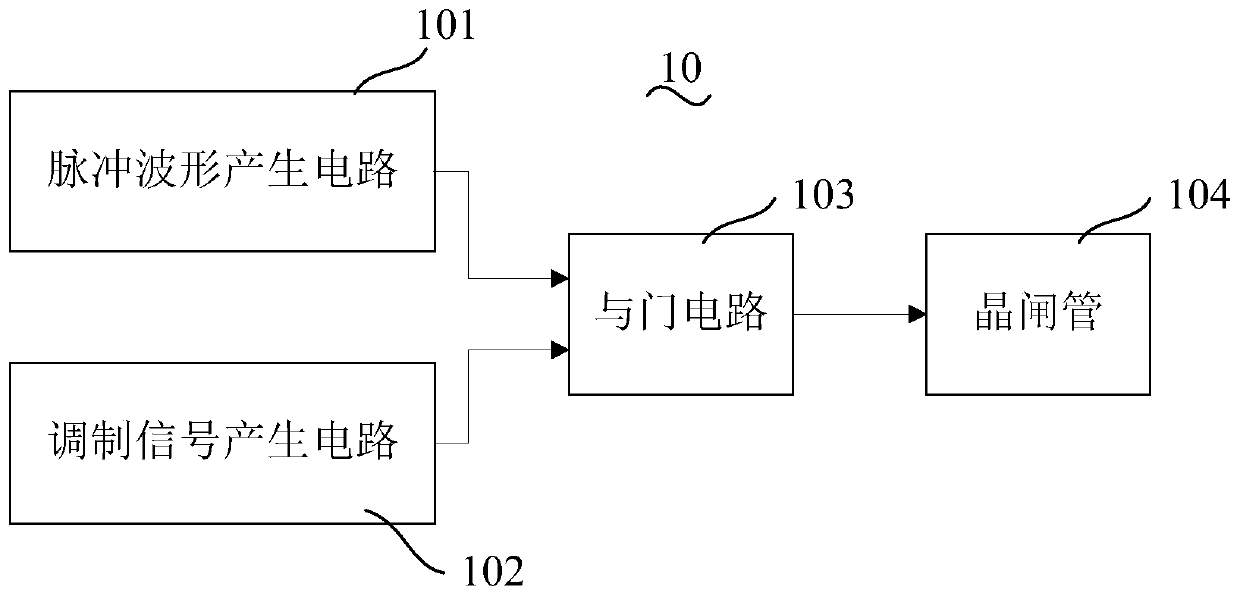
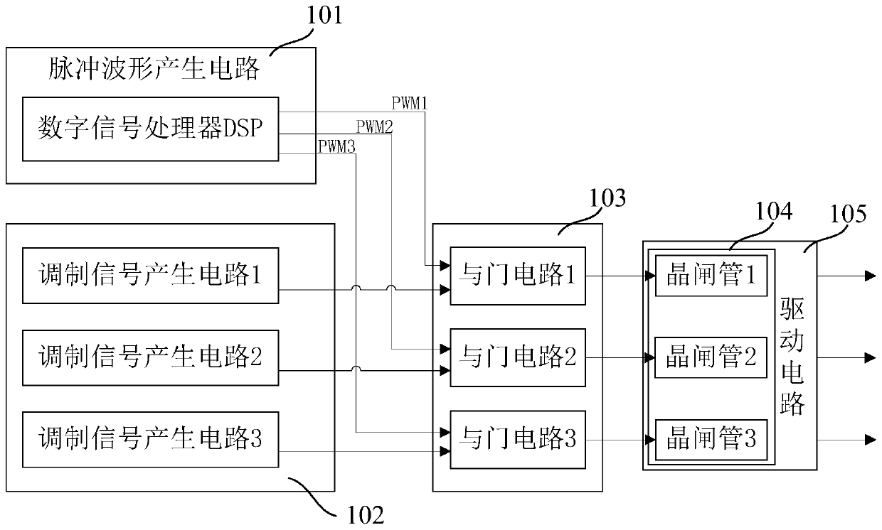
[0026] see figure 1 , which is a block diagram of a pulse modulation circuit 10 for triggering a thyristor in an embodiment. A pulse modulation circuit 10 for triggering a thyristor includes: a pulse waveform generation circuit 101, a modulation signal generation circuit 102, and an AND g...


PUM


Abstract

The invention discloses a pulse modulation circuit for triggering thyristors. The circuit includes a pulse waveform generating circuit, a modulation signal generating circuit and an AND gate circuit.A method for triggering the thyristors is also disclosed. The method includes establishing the pulse waveform generating circuit and the modulation signal generating circuit; generating a pulse widthmodulation waveform through the pulse waveform generating circuit, and generating a pulse width modulation signal through the modulation signal generating circuit; performing logic and operation on the pulse width modulation waveform and the pulse width modulation signal, and generating a driving signal; and outputting the driving signal to a thyristor so as to trigger the thyristor. Through the circuit and method, the gate loss of the thyristor of a driving chip can be greatly reduced while accurate trigger angles and trigger energy, namely the pulse action time, are guaranteed, so that the quality of the pulse modulation circuit can be enhanced; and the circuit is simple, reliable and easy in implementation.

Description

technical field [0001] The invention relates to the technical field of trigger circuits, in particular to a pulse modulation circuit and method for triggering a thyristor. Background technique [0002] Thyristors are widely used in power electronics, motor control, high-power frequency conversion and other fields due to their high voltage, high current and reliable and stable characteristics. In conventional applications, it is generally generated by a microcontroller such as DSP (Digital Signal Processing), MCU (Microcontroller Unit, Microcontroller Unit), FPGA (Field-Programmable Gate Array, Field-Programmable Gate Array), etc. The PWM (Pulse Width Modulation, PulseWidth Modulation) wave directly drives the thyristor after a stage of power amplification, so that the thyristor is turned on. [0003] However, the above-mentioned driving method has high requirements on the performance of the thyristor driver chip itself. Since the driver chip is triggered at full duty within...

Claims


Application Information

Patent Timeline
Patent Type & Authority Patents(China)
IPC IPC(8): H02M1/06H03K17/08
CPCH02M1/06H03K17/08
Inventor 陈广辉乔一伦刘敏通王鹏
Owner GREE ELECTRIC APPLIANCES INC
Why Eureka
Try Eureka