Wound rotor or stator and manufacturing method

A technology of winding rotors and stators, which is applied in the field of manufacturing tooth-shaped winding stators, and can solve the problems of time-consuming winding operations and obstacles

Pending Publication Date: 2019-09-10
MOTEURS LEROY SOMER
View PDF7 Cites 0 Cited by
  • Summary
  • Abstract
  • Description
  • Claims
  • Application Information

AI Technical Summary

Problems solved by technology

[0003] This winding technique is called "fly-winding" and is extremely fast, but is only used on machines with four poles, because with a higher number of poles, the pole shoes of the teeth prevent a

Method used


Image

  • Wound rotor or stator and manufacturing method
  • Wound rotor or stator and manufacturing method
  • Wound rotor or stator and manufacturing method

Examples


Embodiment Construction

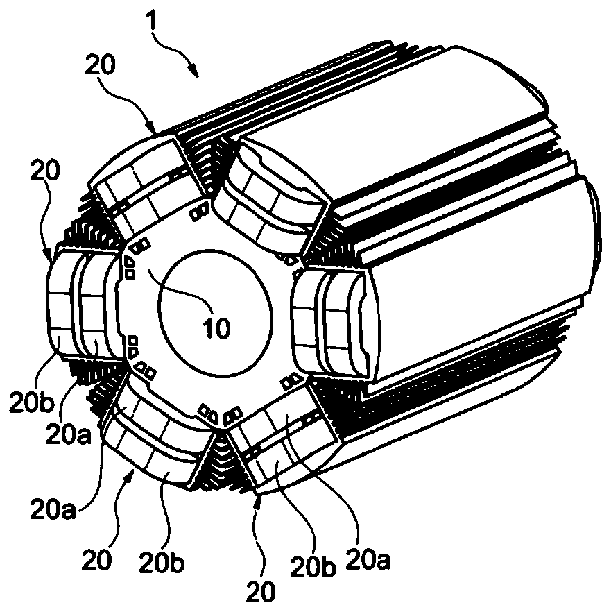
[0034] The rotor 1 according to the invention shown in the figures comprises a magnetic core 10 which is called an armature and which may be formed by a bundle of superimposed magnetic plates.

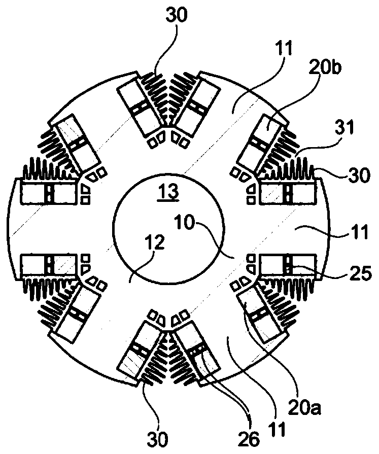
[0035] This magnetic core 10 comprises teeth 11 connected at their bases by an annular part 12 provided with a central hole 13 for mounting a shaft, not shown.

[0036] In the example considered, the rotor 1 has six poles and comprises six teeth 11 .

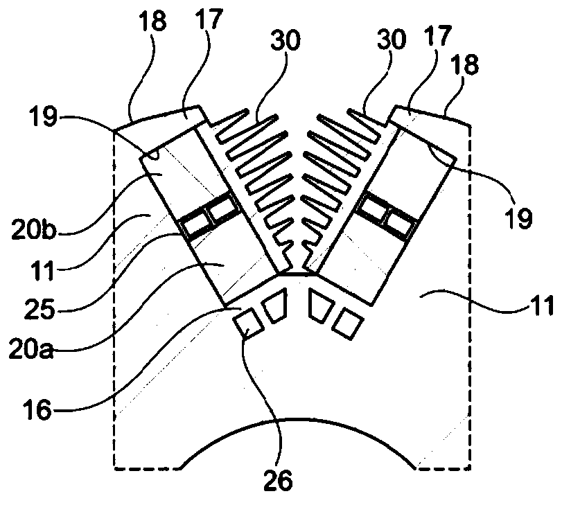
[0037] Vent channels 14 may be made between the teeth 11 as shown. These channels 14 may be formed between the annular part 12 and a partition 16 oriented at right angles to the longitudinal axis X of the adjacent tooth 11 .

[0038] In the example shown, each tooth 11 has two channels 14 on each side of its base, it being understood that other arrangements without ventilation channels, or with a different number of channels, are possible.

[0039] Each tooth 11 has at its radially outermost end two pole shoes 17 , also called pole tip...


PUM


Abstract

Provided is a method for manufacturing a wound rotor or a stator (1) having more than four poles, preferably a rotor, the rotor or stator having teeth (11) provided with pole shoes (17). The method includes the following steps, for each pole: (a) producing a partial winding by winding at least one conductor over the portion of the tooth of this pole extending axially along this pole between the pole shoes of this pole and a plane (Pmin) at right angles to the axis of the pole and tangential to a pole shoe of an adjacent pole, (b) pushing back the duly produced partial winding towards the baseof the tooth, and freeing said portion (32) of the tooth having been used for the winding, and (c) repeating step (a) to produce another partial winding (20b) on the duly released portion of tooth.

Description

technical field [0001] This invention relates to the manufacture of wound rotors for rotating electric machines. The invention also applies to the manufacture of toothed wound stators. Background technique [0002] It is known practice to make a wound rotor of a motor with four poles using a winding machine comprising an arm arranged to wind the wire over the entire height of each tooth of the rotor. [0003] This winding technique is called "fly-winding" and is extremely fast, but is only used on machines with four poles, because with a higher number of poles, the pole shoes of the teeth prevent access through the vicinity of the teeth. tooth operation. [0004] Therefore, the winding of machine rotors with more than four poles is done using more complex techniques and the winding operation takes longer. [0005] An example of a machine developed for winding rotors with more than four poles is described in patent US 4340186 . [0006] There is a need to further improve ...

Claims


Application Information

Patent Timeline
IPC IPC(8): H02K15/08
CPCH02K15/08H02K1/20H02K1/32H02K3/24H02K15/0031H02K15/066H02K15/095H02K15/022H02K1/14H02K1/24H02K3/18H02K9/10H02K15/062
Inventor 雅克·圣-米歇尔
Owner MOTEURS LEROY SOMER
Why Eureka
Try Eureka