
Oscillation circuit

A crystal oscillator circuit and circuit technology, applied in the direction of electrical components, electric pulse generation, pulse technology, etc., can solve the problems of inability to solve the problem of start-up time and low power consumption design, crystal oscillator circuit is not suitable, achieve fast start-up, reduce power consumption effect

Active Publication Date: 2019-09-10
BYD SEMICON CO LTD
View PDF8 Cites 7 Cited by
  • Summary
  • Abstract
  • Description
  • Claims
  • Application Information

AI Technical Summary

Problems solved by technology

But this is to sacrifice the power consumption in exchange for the start-up time, which cannot solve the contradiction between the start-up time and low power consumption design, especially in many occasions requiring low power consumption, such a crystal oscillator circuit is not suitable

Method used


Image

  • Oscillation circuit
  • Oscillation circuit
  • Oscillation circuit

Examples


Embodiment Construction

[0018] Embodiments of the present invention are described in detail below, examples of which are shown in the drawings, wherein the same or similar reference numerals designate the same or similar elements or elements having the same or similar functions throughout. The embodiments described below by referring to the figures are exemplary and are intended to explain the present invention and should not be construed as limiting the present invention.

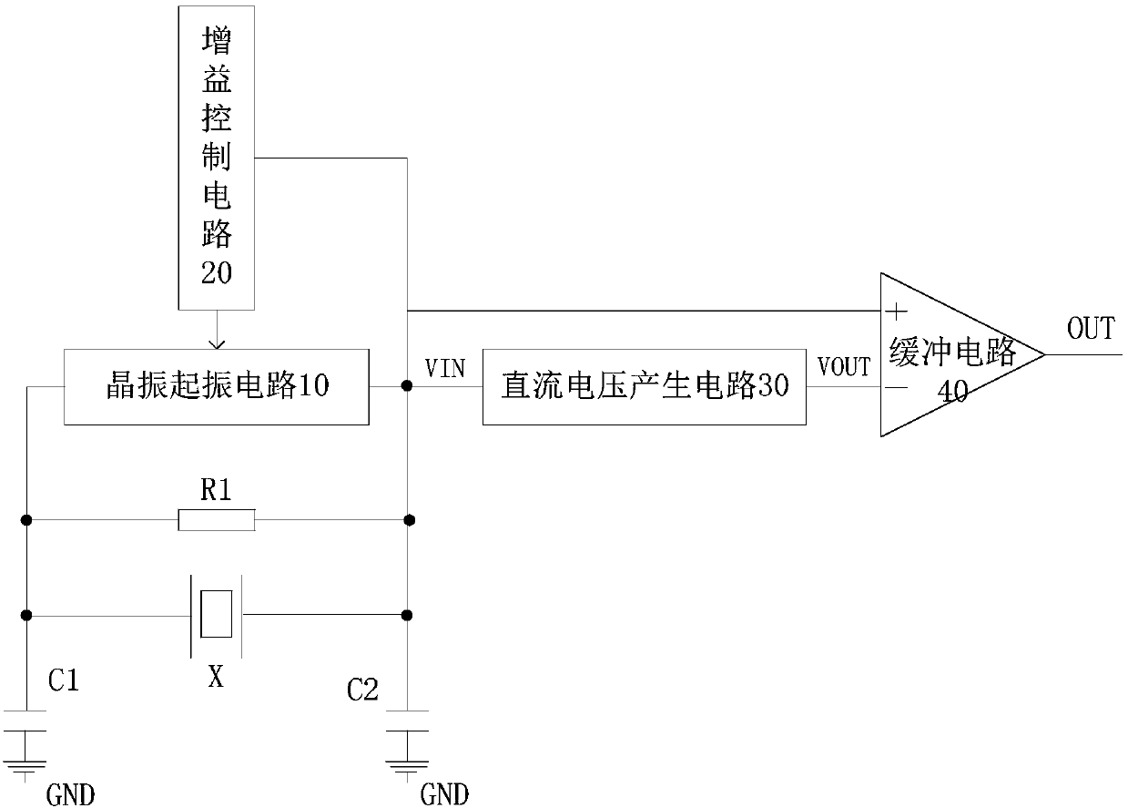
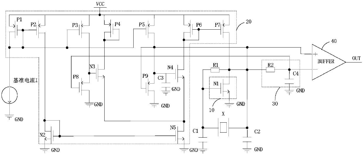
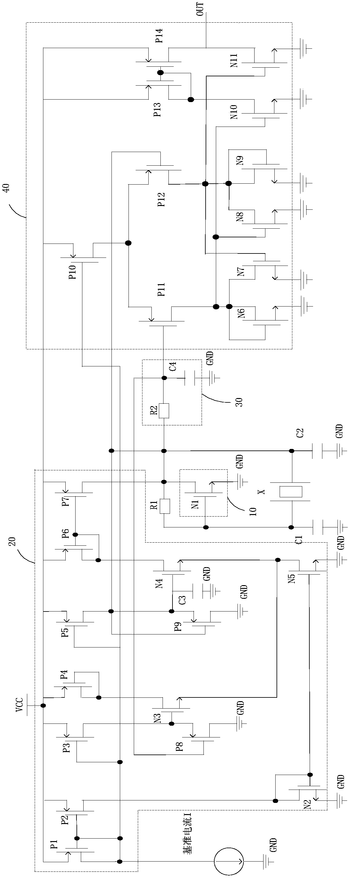
[0019] figure 1 is a schematic structural diagram of a crystal oscillator circuit according to an embodiment of the present invention. Such as figure 1 As shown, the crystal oscillator circuit 100 includes a crystal oscillator starting circuit 10 , a gain control circuit 20 , a DC voltage generating circuit 30 and a buffer circuit 40 .

[0020] refer to figure 1 , the first end and the second end of the crystal oscillator circuit 10 are connected to the two ends of the passive crystal oscillator X, and a feedback resistor R1 i...


PUM


Abstract

The invention discloses an oscillation circuit which comprises a crystal oscillator oscillation starting circuit. A first end and a second end of the crystal oscillator oscillation starting circuit are connected to the two ends of a passive crystal oscillator, and a feedback resistor is connected between the first end and the second end of the crystal oscillator oscillation starting circuit. The gain control circuit is respectively connected with the crystal oscillator oscillation starting circuit and the passive crystal oscillator and is used for detecting the amplitude of the passive crystaloscillator and adjusting the current of the crystal oscillator oscillation starting circuit according to the amplitude of the passive crystal oscillator so as to enable the amplitude of the passive crystal oscillator to reach a preset value. The direct-current voltage generation circuit is connected with the crystal oscillator oscillation starting circuit and used for generating a direct-currentvoltage signal according to the alternating-current voltage signal output by the crystal oscillator oscillation starting circuit. The first input end of the buffer circuit is connected with the outputend of the crystal oscillation starting circuit, and the second input end of the buffer circuit is connected with the output end of the direct-current voltage generation circuit and used for conducting difference according to the direct-current voltage signal and the alternating-current voltage signal so as to output a clock signal. According to the oscillation circuit, power consumption can be reduced, and meanwhile rapid oscillation starting of the crystal oscillator is achieved.

Description

technical field [0001] The invention relates to the field of integrated circuits, in particular to an oscillation circuit. Background technique [0002] Quartz crystal oscillator is a resonant device made by using the piezoelectric effect of quartz crystal. Because quartz crystal has a very high quality factor, quartz crystal oscillator can generate accurate and stable oscillation waveforms, and is widely used for vibration Clocks and watches, military industry, communication and other fields with high frequency requirements. [0003] With the rapid development of portable devices in the communication field in recent years, the design requirements for integrated circuits with low power consumption and low cost have become increasingly prominent. Among the multiple design indicators of the crystal oscillator circuit, the start-up time is particularly important, especially for some integrated circuits that require a fast clock to complete initialization. [0004] In the rela...

Claims


Application Information

Patent Timeline
Patent Type & Authority Applications(China)
IPC IPC(8): H03K3/012
CPCH03K3/012
Inventor 陈胜胜李奇峰杨云
Owner BYD SEMICON CO LTD
Learn More