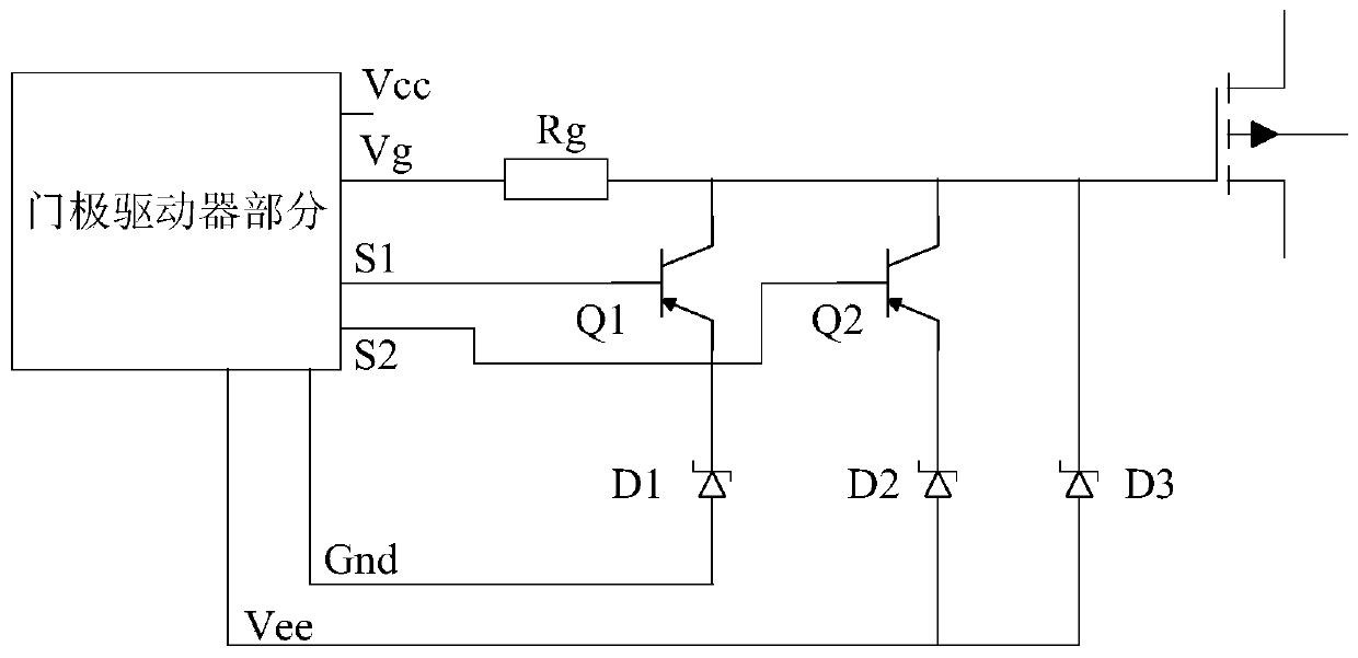
Driving protection circuit

A technology for driving protection circuits and drivers, which is applied in the direction of logic circuit interface devices, logic circuit connection/interface layout, elimination of voltage/current interference, etc., can solve the problems of field effect transistors such as easy misconduct, and achieve the effect of improving stability

Active Publication Date: 2019-09-10
GREE ELECTRIC APPLIANCES INC
View PDF8 Cites 2 Cited by
  • Summary
  • Abstract
  • Description
  • Claims
  • Application Information

AI Technical Summary

Problems solved by technology

[0006] The main purpose of the present invention is to provide a driving protection circuit to solve the problem that field effect transistors are easily misconducted at high switching frequencies

Method used


Image

  • Driving protection circuit

Examples


Embodiment Construction

[0020] It should be noted that, in the case of no conflict, the embodiments in the present application and the features in the embodiments can be combined with each other. The present invention will be described in detail below with reference to the accompanying drawings and examples.

[0021] In order to enable those skilled in the art to better understand the solution of the present application, the technical solution in the embodiment of the application will be clearly and completely described below in conjunction with the accompanying drawings in the embodiment of the application. Obviously, the described embodiment is only It is an embodiment of a part of the application, but not all of the embodiments. Based on the embodiments in this application, all other embodiments obtained by persons of ordinary skill in the art without creative efforts shall fall within the scope of protection of this application.

[0022] It should be noted that the terms "first" and "second" in ...


PUM


Abstract

The invention discloses a driving protection circuit. The circuit includes: a gate driver; a first triode the gate electrode of which is connected with the first port of the gate electrode driver, andthe drain electrode of which is connected with the grounding end of the gate electrode driver; a second triode the gate electrode of which is connected with the second port of the gate electrode driver, and the drain electrode of which is connected with the third port of the gate electrode driver; a third voltage stabilizing diode the positive electrode of which is connected with the third port of the gate driver, and the negative electrode of which is connected with the fourth port of the gate driver; and a field effect transistor which is connected with the fourth port of the gate driver and the negative electrode of the third voltage stabilizing diode. According to the invention, the effect of improving the stability of the field effect transistor is achieved.

Description

technical field [0001] The invention relates to the field of circuits, in particular to a driving protection circuit. Background technique [0002] With the continuous development of the new generation of wide bandgap semiconductor technology and structure, devices represented by SiC and GaN have been increasingly used in various fields, and SiC MOS tubes are widely used. SiC MOSFET has the advantages of high switching frequency, small size, high temperature resistance, etc., but high frequency operation also brings new problems. The gate turn-on threshold voltage of SiC MOSFET itself is relatively low, generally around 2.2V, and as the temperature rises, this threshold voltage will decrease, so the switching tube is more likely to be misconducted when the gate is disturbed. [0003] For example, when the system is turned off at high frequency, a large di / dt will be generated on the system. At this time, a voltage will be generated on the stray inductance of the gate. If th...

Claims


Application Information

Patent Timeline
Patent Type & Authority Applications(China)
IPC IPC(8): H03K19/0175H03K19/003
CPCH03K19/00307H03K19/00315H03K19/00353H03K19/00361H03K19/017518
Inventor 刘敏通刘江吴中建
Owner GREE ELECTRIC APPLIANCES INC
Why Eureka
Try Eureka