
High-pressure fuel pump

A high-pressure pump and fuel technology, which is used in fuel injection pumps, fuel injection devices, liquid fuel engines, etc., to simplify the deburring method, reduce costs, and improve service life.

Active Publication Date: 2019-09-13
ROBERT BOSCH GMBH
View PDF8 Cites 0 Cited by
  • Summary
  • Abstract
  • Description
  • Claims
  • Application Information

AI Technical Summary

Problems solved by technology

[0004]The problem on which the invention is based is solved by the fuel high pressure pump according to the invention

Method used


Image

  • High-pressure fuel pump
  • High-pressure fuel pump
  • High-pressure fuel pump

Examples


Embodiment Construction

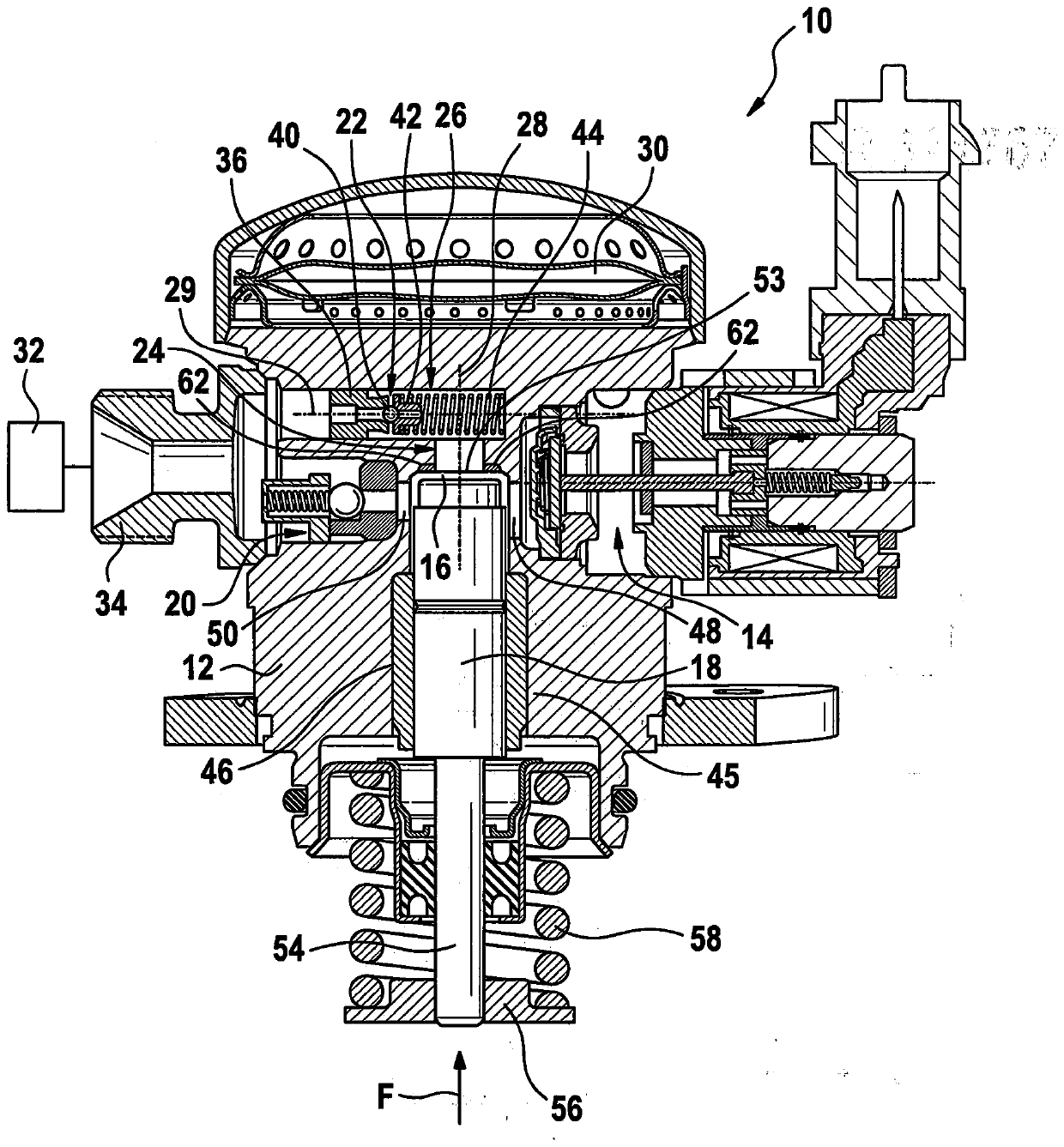
[0023] exist figure 1 10 , the high-pressure fuel pump for an internal combustion engine, not shown in detail, is generally designated 10 . The high-pressure fuel pump 10 has an overall substantially cylindrical pump housing 12 in or on which the main components of the high-pressure fuel pump 10 are arranged. The high-pressure fuel pump 10 has an inlet / flow control valve 14 , a delivery piston 18 arranged in a delivery chamber 16 , an outlet valve 20 and a pressure limiting valve 22 .

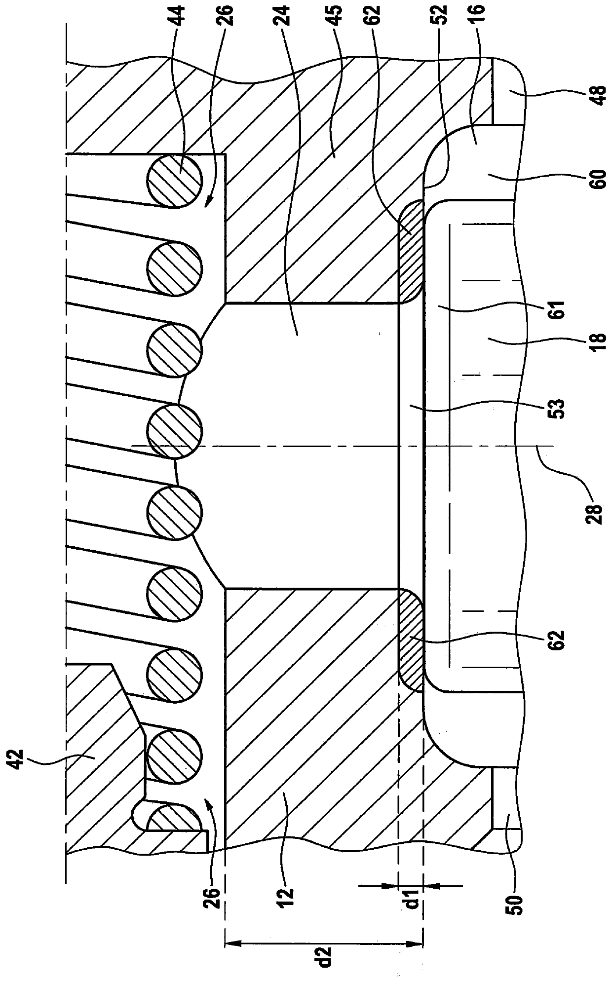
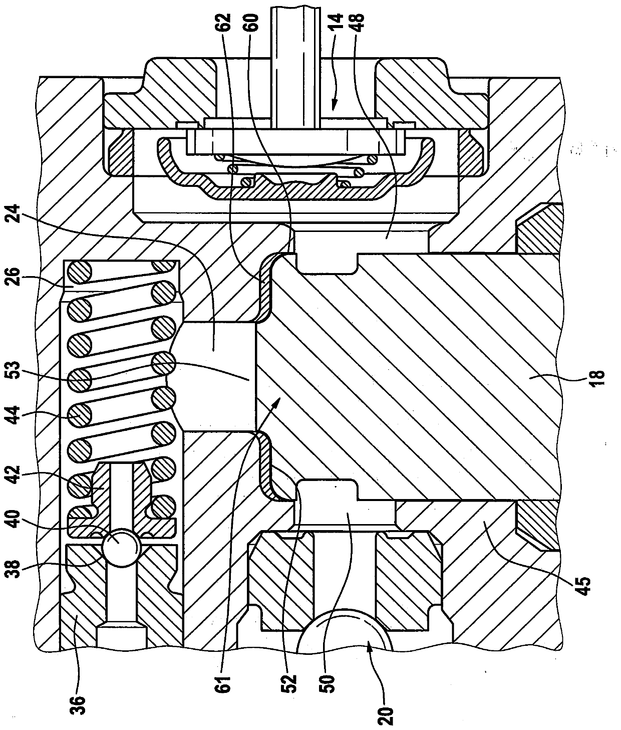
[0024] In the housing 12 there is a first channel 24 which extends coaxially to the delivery chamber 16 and the delivery piston 18 and leads from the delivery chamber 16 to a second channel 26 in the form of an overall substantially cylindrical groove, The groove is arranged at an angle of 90° to the first channel 24 and the pressure limiting valve 22 is received in the groove. The longitudinal axis of the pump housing 12 is at figure 1 The center generally bears the reference number 28 , th...


PUM


Abstract

The invention relates to a high-pressure fuel pump (10) for a fuel injection system of an internal combustion engine. The high-pressure fuel pump comprises a delivery piston (18) delimiting a deliverychamber (16) for delivering fuel, and a piston housing (45) surrounding the delivery piston (18), the piston housing (45) having a housing bottom (52) which likewise delimits the delivery chamber (16), the housing bottom (52) being plastically deformed at least in sections.

Description

technical field [0001] The invention relates to a high-pressure fuel pump. The invention also relates to a method corresponding to the high-pressure fuel pump. Background technique [0002] Fuel systems for internal combustion engines, such as high-pressure fuel pumps for gasoline direct injection, are known on the market. In these internal combustion engines, fuel is conveyed under high pressure from a fuel tank into a high-pressure accumulator (“rail”) by means of a prefeed pump and a mechanically driven high-pressure pump. [0003] Such fuel systems usually have a delivery piston which, during an intake stroke, draws fuel into the delivery chamber via an inlet and a flow control valve. During the delivery stroke, the fuel located in the delivery chamber is compressed and discharged via an outlet valve, in particular into a high-pressure region, for example to a fuel collecting line (“rail”), where the fuel is stored under high pressure. Contents of the invention [0...

Claims


Application Information

Patent Timeline
Patent Type & Authority Applications(China)
IPC IPC(8): F02M59/44F02M59/02F04B53/16
CPCF02M59/44F02M59/02F04B53/16F02M59/48F02M59/102F02M59/445F04B1/0404F04B1/053F04B11/0033F04B53/1082F02M59/025
Inventor D·贝克曼E-A·利纳特H·雅恩P·赖歇特R·博恩
Owner ROBERT BOSCH GMBH
Learn More