A mems inertial sensor based on diamagnetic levitation

An inertial sensor and anti-magnet technology, applied in the field of MEMS inertial sensors, can solve problems affecting sensor performance, energy dissipation, resolution-limited noise level, etc., and achieve the effect of increasing the difficulty of production and easy implementation

Active Publication Date: 2020-09-08
HUAZHONG UNIV OF SCI & TECH
View PDF8 Cites 0 Cited by
  • Summary
  • Abstract
  • Description
  • Claims
  • Application Information

AI Technical Summary

Problems solved by technology

[0006] Aiming at the defects of the prior art, the purpose of the present invention is to solve the problem that the existing gravitational acceleration sensor requires external energy, the spring and the mass block directly contact to generate friction, the friction affects the performance of the sensor, energy dissipation, and its resolution is limited The noise level of the system and the technical problems that the existing MEMS gravity acceleration sensor cannot take advantage of the MEMS process

Method used


Image

  • A mems inertial sensor based on diamagnetic levitation
  • A mems inertial sensor based on diamagnetic levitation
  • A mems inertial sensor based on diamagnetic levitation

Examples


Embodiment Construction

[0037] In order to make the objectives, technical solutions and advantages of the present invention clearer, the following further describes the present invention in detail with reference to the accompanying drawings and embodiments. It should be understood that the specific embodiments described herein are only used to explain the present invention, but not to limit the present invention. In addition, the technical features involved in the various embodiments of the present invention described below can be combined with each other as long as they do not conflict with each other.

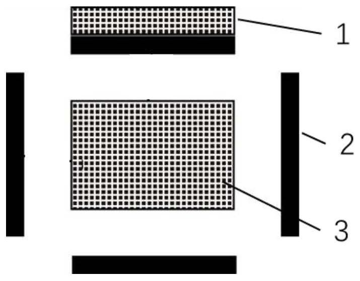
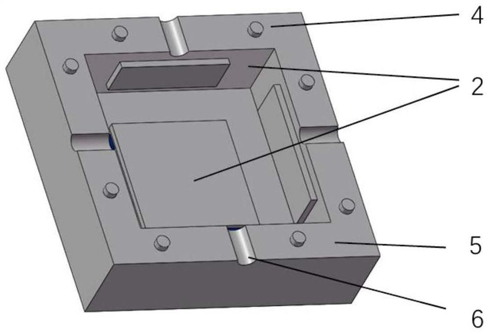
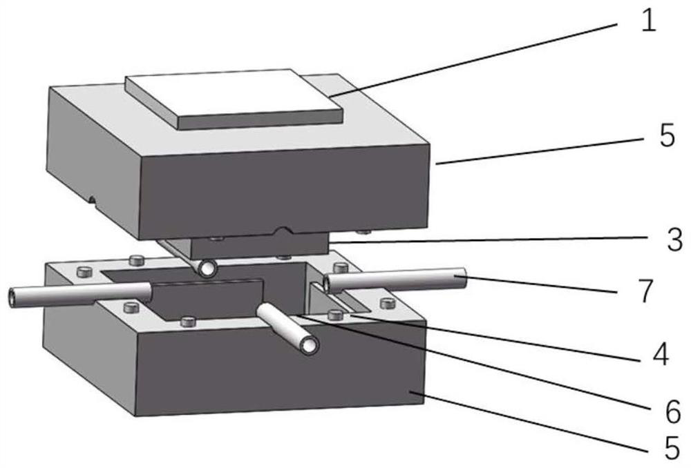
[0038] In view of the existing anti-magnetic levitation technology, the purpose of the present invention is to provide an inertial sensor based on diamagnetic levitation using SOI chips, wherein the MEMS inertial sensor is obtained by selecting the key device layer and support layer in the manufacturing method, which is consistent with the prior art. Compared with the effective production of the requir...


PUM

PropertyMeasurementUnit
thicknessaaaaaaaaaa
thicknessaaaaaaaaaa
thicknessaaaaaaaaaa

Abstract

The invention discloses an MEMS (Micro-Electro-Mechanical System) inertial sensor based on diamagnet suspension. The MEMS inertial sensor comprises deep silicon etched grooves, a suspended permanent magnet, a fixed permanent magnet and diamagnetic materials, wherein the deep silicon etched grooves internally have closed spaces and are obtained by etching out middle regions of supporting layers inSOI silicon chips; the suspended permanent magnet is positioned in the closed spaces of the deep silicon etched grooves; the fixed permanent magnet is fixed to the top outside an upper etched groove and is used for providing a suspension force acted on the suspended permanent magnet to overcome a gravity of the suspended permanent magnet, so that the suspended permanent magnet is suspended in theclosed spaces; the diamagnetic materials are symmetrically fixed inside the deep silicon etched grooves and provides symmetrical diamagnetic forces to the suspended permanent magnet; when the MEMS inertial sensor is applied with an external acting force to cause a change of a position of the suspended permanent magnet, the diamagnetic forces are used as elasticity-like resilience forces for restraining the position of the suspended permanent magnet; and a displacement of the suspended permanent magnet is used for determining a spatial inertial acceleration corresponding to the external actingforce. The inertial sensor disclosed by the invention is not influenced by a friction force.

Description

Technical field [0001] The present invention relates to the technical field of processing and manufacturing of microelectronic devices, and more specifically, to a MEMS inertial sensor based on anti-magnet suspension. Background technique [0002] Near the surface, the earth's gravitational field is one of the most basic and important physical fields, which is of great significance to the precise measurement of the gravitational field. Gravity measurement has broad application prospects in resource exploration, auxiliary navigation, national defense and military, and earth sciences. Taking the gravity acceleration sensor as an example, the gravity acceleration sensor is a precision gravity measurement sensor that measures the small changes in the acceleration of gravity. [0003] The basic model of the mechanical structure of the gravity acceleration sensor is a spring-vibrator structure, which is composed of a spring, a test mass, and damping caused by air or structure. The test ...

Claims


Application Information

Patent Timeline
Patent Type & Authority Patents(China)
IPC IPC(8): G01V7/00G01V7/02G01P15/08G01P15/03G01P1/00
CPCG01P1/00G01P15/03G01P15/08G01P15/0802G01V7/00G01V7/02
Inventor 王秋刘骅锋胡宸源涂良成
Owner HUAZHONG UNIV OF SCI & TECH
Why Eureka
Try Eureka