Main outgoing line improvement mechanism of through-flow hydropower station generator

A hydroelectric power generator, through-flow technology, applied in the direction of using the reel/photosensitive drum layout, etc., can solve the problems of inability to use, inability to move and adjust, inability to connect, etc., to avoid direct connection , Increase the length and shorten the connection distance

Active Publication Date: 2019-09-13
贵州水利水电职业技术学院
View PDF6 Cites 2 Cited by
  • Summary
  • Abstract
  • Description
  • Claims
  • Application Information

AI Technical Summary

Problems solved by technology

Although this structure shortens the connection distance of the busbar, it still has limitations. The cables and copper bars of this structure are fixed and cannot be moved a

Method used


Image

  • Main outgoing line improvement mechanism of through-flow hydropower station generator
  • Main outgoing line improvement mechanism of through-flow hydropower station generator

Examples


Embodiment 1

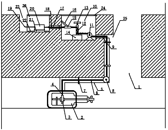
[0024] see Figure 1~2 , in an embodiment of the present invention, an improved mechanism for the main lead-out line of a tubular hydropower station generator includes a water turbine well 1, and a water turbine 2 is installed in the water turbine well 1, through which the energy of the water flow is converted into rotational mechanical energy , the water turbine 2 is protected by a protective cover, which can improve the stability of the water turbine 2, the water turbine 2 is provided with a stator 3, the stator 3 is connected to the cable 6 through the stator copper bar 4, and the stator 3, the stator copper bar 4 and the The cable 6 can transfer corresponding energy, so it can be used in daily life.

[0025] Further, the cable 6 is arranged in the connecting pipe 5, and the cable 6 is protected through the connecting pipe 5, which avoids the problem that the cable 6 is damaged by water, and has a very good protective effect. The connecting pipe 5 is arranged in the water t...

Embodiment 2

[0030] The difference between the embodiment of the present invention and embodiment 1 is that the top of the first equipment room 10 and the second equipment room 26 are provided with a cover plate 24, and the first equipment room 10 and the second equipment room 26 can be controlled by the cover plate 24. Cover to prevent people from getting lost. When it is necessary to increase the length of the connection, open the cover plate 24 and enter the first equipment room 10 and the second equipment room 26.

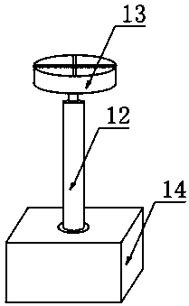
[0031] The working principle of the present invention is: when it is necessary to adjust the length of the connecting line, open the cover plate 24, enter the first equipment room 10 and the second equipment room 26, and by turning the rotating shaft 12, the cable 6 in the connecting pipe 5 will be straightened, thereby The length of the cable 6 in the first equipment room 10 and the second equipment room 26 is increased. By moving the slider 21, the length of the copper bar...


PUM


Abstract

The invention discloses a main outgoing line improvement mechanism of a through-flow hydropower station generator, relates to the field of hydropower station generators, and mainly aims to solve the problem that copper bars and circuit lengths cannot be adjusted. The main outgoing line improvement mechanism of the through-flow hydropower station generator comprises a hydraulic turbine well which is internally provided with a hydraulic turbine, a stator is arranged in the hydraulic turbine, the stator is connected with a cable through a stator copper bar, the cable enters a first device chamberthrough a first connection pipe, the first device chamber is internally provided with a second runner, one side of the second runner is provided with a rotating shaft, the first device chamber is connected with a second device chamber through a second connection pipe, the second device chamber is internally provided with a current transformer, the stator copper bar passes through the current transformer and is connected with the copper bar, the copper bar is led out to a lead-out adit so as to improve the stability of the cable and conveniently adjust the length of the cable.

Description

technical field [0001] The invention relates to the field of hydropower generators, in particular to an improved mechanism for the main lead-out line of a tubular hydropower generator. Background technique [0002] A tubular turbine is a horizontal-axis turbine, that is, the water flow basically moves along the horizontal axis in the flow channel. It is mainly suitable for water heads of 1 to 25m, and is a special model for low water head and large flow hydropower stations. Since the water flow basically moves axially in the flow channel without turning, the water passing capacity and hydraulic efficiency of the unit can be improved. It is especially suitable for tidal power stations, and its functions of two-way power generation, two-way pumping and two-way discharge are very suitable for comprehensive utilization of low-head hydraulic resources. [0003] Application publication number CN109742652A discloses the improved structure of the main lead-out line of the generato...

Claims


Application Information

Patent Timeline
IPC IPC(8): H02G11/02
CPCH02G11/02
Inventor 张蓉蓉
Owner 贵州水利水电职业技术学院
Why Eureka
Try Eureka