Road remote street lamp fault monitoring and indicating system

A technology of fault monitoring and fault indication, applied in the direction of lamp circuit layout, lighting devices, light sources, etc., can solve the problems of reducing the timeliness of repairing faulty street lamps, waste of resources, and inconvenience to staff, so as to realize automatic positioning and tracking work and improve work efficiency. Efficiency, ensure the effect of timeliness

Inactive Publication Date: 2019-09-13
ZHONGSHAN GUIYUAN OPTOELECTRONICS TECH CO LTD
View PDF5 Cites 4 Cited by
  • Summary
  • Abstract
  • Description
  • Claims
  • Application Information

AI Technical Summary

Problems solved by technology

[0003] At present, the urban lighting system adopts the traditional light control or time control control method, and the fault monitoring of road street lamps is mostly carried out manually one by one. The work efficiency is low, the maintenance of faulty street lamps is more inconvenient, and the street lamps mostly run all night , the brightness of street lamps cannot be adjusted according to the surrounding light intensity, resulting in waste of resources, poor energy saving and environmental protection effects, and no automatic positioning function, unable to repair faulty street lamps in time, which brings inconvenience to the staff and reduces the maintenance cost of faulty street lamps Timeliness, therefore, those skilled in the art provide a road remote street lamp failure monitoring and indication system to solve the problems raised in the above-mentioned background technology

Method used


Image

  • Road remote street lamp fault monitoring and indicating system
  • Road remote street lamp fault monitoring and indicating system

Examples


Embodiment Construction

[0024] The following will clearly and completely describe the technical solutions in the embodiments of the present invention with reference to the accompanying drawings in the embodiments of the present invention. Obviously, the described embodiments are only some, not all, embodiments of the present invention. Based on the embodiments of the present invention, all other embodiments obtained by persons of ordinary skill in the art without making creative efforts belong to the protection scope of the present invention.

[0025] see Figure 1~2 , in the embodiment of the present invention,

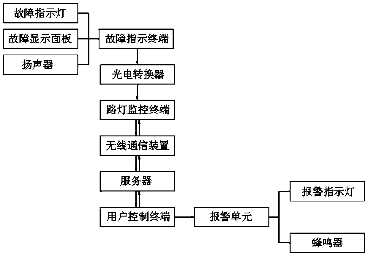
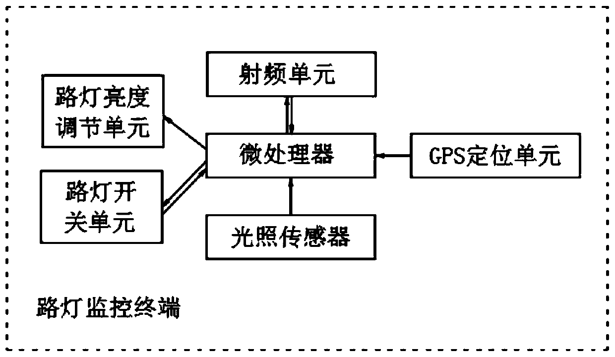
[0026] A road remote street lamp fault monitoring and indicating system, including a fault indicating terminal, and also includes a photoelectric converter, a street lamp monitoring terminal, a wireless communication device, a server, a user control terminal and an alarm unit, and the street lamp fault indicating terminal and the street lamp monitoring terminal pass through a photoelectric ...


PUM


Abstract

The present invention discloses a road remote street lamp fault monitoring and indicating system, pertaining to the technical field of street lamp fault monitoring. The system comprises a fault indication terminal. The system also comprises a photoelectric converter, a street lamp monitoring terminal, a wireless communication device, a server, a user control terminal and an alarm unit. The streetlamp fault indication terminal is connected with the street lamp monitoring terminal via the photoelectric converter, and the street lamp monitoring terminal is arranged at a street lamp. In the actual use process, street lamp fault signal(s) are transmitted to the street lamp monitoring terminal via the fault indication terminal, the street lamp monitoring terminal sends the street lamp fault signal(s) to the server via the wireless communication device, and the server sends the street lamp fault signal(s) to the user control terminal. According to the system, the remote monitoring work of the street lamp fault(s) is realized, the defect that the conventional street lamp fault(s) require manual one-by-one inspection, is overcome, and the working efficiency is effectively improved. The system can provide convenience for the maintenance and the repair of the street lamp(s) and ensure timeliness of street lamp maintenance.

Description

technical field [0001] The invention relates to the technical field of street lamp fault monitoring, in particular to a remote road lamp fault monitoring and indicating system. Background technique [0002] Street lamps are an indispensable basic public facility for people's daily life. With the rapid development of the economy and the increase of road loads, road safety has attracted more and more attention from people. The rapid development of road lighting in cities has led to corresponding power consumption. With the rapid development of urban construction, especially the extensive implementation of urban lighting projects such as road lighting and landscape lighting, the scale of urban lighting systems is becoming larger and larger, and the number of various lighting facilities and equipment is also increasing. It is an urgent need to improve the unified management of the street lighting system. [0003] At present, the urban lighting system adopts the traditional ligh...

Claims


Application Information

Patent Timeline
Patent Type & Authority Applications(China)
IPC IPC(8): H05B37/03H05B37/02G08B21/24
CPCG08B21/24H05B47/20H05B47/105Y02B20/40
Inventor 宫成喆
Owner ZHONGSHAN GUIYUAN OPTOELECTRONICS TECH CO LTD
Why Eureka
Try Eureka