
Mixing barrel for coal water slurry additive

A mixing tank and additive technology, which is applied to mixer accessories, mixers with rotating stirring devices, mixers, etc., can solve the problems of mixing dead angle, equipment cleanliness, and low mixing efficiency, so as to avoid mixing dead angle and reduce resources Damage, the effect of improving stirring efficiency

Pending Publication Date: 2019-09-17
江苏合义化工新材料有限公司
View PDF0 Cites 0 Cited by
  • Summary
  • Abstract
  • Description
  • Claims
  • Application Information

AI Technical Summary

Problems solved by technology

[0002] CWS additives often need to be stirred during the preparation process, and the particle size of solid raw materials has a direct impact on the product; solid raw material particles may be affected by moisture during the process of preparation, transportation, and storage, and the moisture of solid raw materials may affect water coal. The production quality of slurry additives is affected; solid raw materials may adhere to the surface of conveyor belts and grinding rollers during drying, crushing and screening, which will not only cause loss of raw materials, but also reduce the cleanliness inside the equipment; mixing equipment During the stirring operation, there may be a stirring dead angle at the inner bottom corner of the mixing equipment, resulting in the accumulation of materials, and raw materials may adhere to the inner end wall of the mixing equipment, which will cause the loss of raw materials and also affect the subsequent CWS additives. The preparation is affected; the more common stirring mode is that the motor drives the stirring shaft and the stirring rod to rotate. This kind of stirring mode has low stirring efficiency, so a new solution is needed now

Method used


Image

  • Mixing barrel for coal water slurry additive
  • Mixing barrel for coal water slurry additive
  • Mixing barrel for coal water slurry additive

Examples


Embodiment 1

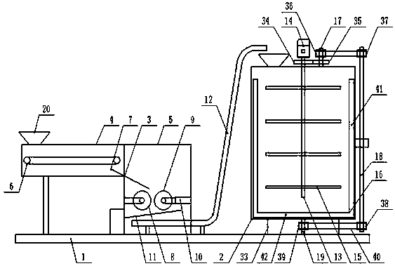
[0017] Embodiment 1: see figure 1 , figure 2 , image 3 , Figure 4 , Figure 5 , Image 6, now a description of a mixing tank for coal-water slurry additives provided by the present invention, including a base base 1, the upper end of the base base 1 is provided with a mixing tank 2, the upper end of the base base 1 is located in the mixing tank 2 A feeding mechanism 3 is provided on the side of the position, and the feeding mechanism 3 includes a feeding box body 4, a grinding box body 5, a conveying assembly 6, an inclined material guide plate 7, an active grinding roller 8, a driven grinding roller 9, a telescopic Cylinder 10, inclined vibrating mesh screen 11 and large inclination angle conveyor 12, the top of the mixing tank 2 is provided with a solid feed port and a liquid feed port, and the inner cavity of the mixing tank 2 is vertically provided with a stirring shaft 13, The outer top of the mixing bucket 2 is provided with a rotating motor 14 and the output sha...

Embodiment 2

[0018] Example 2: see figure 1 , a kind of mixing tank for the additive of coal-water slurry provided by the present invention is described now, and the upper end side of described grinding box body 5 is fixedly provided with described feed box body 4, and described feed box body 4 and described The fixed end faces of the grinding box 5 are all provided with guide ports, and the conveying assembly 6 is arranged in the feeding box 4 and the conveying assembly 6 is an existing equipment belt conveyor, and the feeding box The inner end wall of the body 4 is provided with a heating plate, and the upper end of the feeding box 4 is provided with a feeding port corresponding to the position of the feeding end of the conveying assembly 6. The upper end of the feeding box 4 and the upper end of the mixing barrel 2 are corresponding to The positions of the feeding inlet, the solid feeding inlet, and the liquid feeding inlet are respectively provided with a feeding funnel 20, and an air ...

Embodiment 3

[0019] Embodiment 3: see figure 1 , figure 2 , image 3 Now, a description is given to a mixing tank for coal-water slurry additive provided by the present invention, the inclined material guide plate 7 is arranged through the material guide port, and it is located below the position of the discharge end of the conveying assembly 6, The active grinding roller 8 is arranged in the grinding box 5 and below the position of the bottom end in the inclined direction of the inclined material guide plate 7, and the positions in the grinding box 5 and corresponding to the driving grinding roller 8 are spaced parallel to each other. The driven grinding roller 9 is arranged horizontally, the telescopic cylinder 10 is respectively arranged between the two ends of the length direction of the driven grinding roller 9 and the inner end wall of the grinding box 5, and the active grinding roller 8 An inclined vibrating screen 11 is arranged below the position, and the outer end wall of the ...


PUM


Abstract

The invention discloses a stirring barrel for a coal water slurry additive, the stirring barrel comprises a basic base, and a stirring barrel and a feeding mechanism are arranged at the upper end of the basic base. The feeding mechanism comprises a feeding box body, a grinding box body, a conveying assembly, an inclined material guide plate, a driving grinding roller, a driven grinding roller, a telescopic cylinder, an inclined vibrating mesh screen and a large inclination conveyor; a solid feeding port and a liquid feeding port are arranged at the top of the stirring barrel; a stirring shaft is vertically arranged at the middle side of the inner cavity of the stirring barrel; a rotating motor is arranges at the outer top end of the stirring barrel, an output shaft of the rotating motor is connected with the end part of the top end of the stirring shaft through a coupling, stirring rods are uniformly arranged in the stirring barrel and positioned outside the stirring shaft, a U-shaped stirring frame is arranged in the stirring barrel, a first transmission shaft is arranged at the outer top end of the stirring barrel, a second transmission shaft is arranged at the outer end of the stirring barrel, and a third transmission shaft is arranged in the middle of the bottom end of the stirring barrel.

Description

technical field [0001] The invention relates to the field of coal-water slurry additives, in particular to a mixing tank for coal-water slurry additives. Background technique [0002] CWS additives often need to be stirred during the preparation process, and the particle size of solid raw materials has a direct impact on the product; solid raw material particles may be affected by moisture during the process of preparation, transportation, and storage, and the moisture of solid raw materials may affect water coal. The production quality of slurry additives is affected; solid raw materials may adhere to the surface of conveyor belts and grinding rollers during drying, crushing and screening, which will not only cause loss of raw materials, but also reduce the cleanliness inside the equipment; mixing equipment During the stirring operation, there may be a stirring dead angle at the inner bottom corner of the mixing equipment, resulting in the accumulation of materials, and raw...

Claims


Application Information

Patent Timeline
IPC IPC(8): B01F7/18B01F3/20B01F15/00B01F23/70
CPCB01F23/71B01F23/713B01F27/90B01F35/123B01F2101/501
Inventor 沈健何其慧沈佩章峻蒋雪峰莫宏
Owner 江苏合义化工新材料有限公司
Learn More