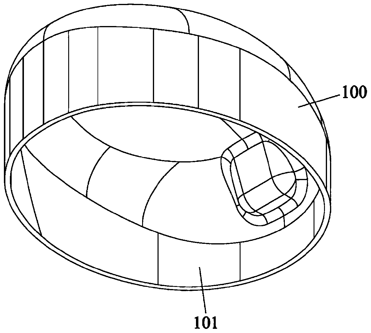
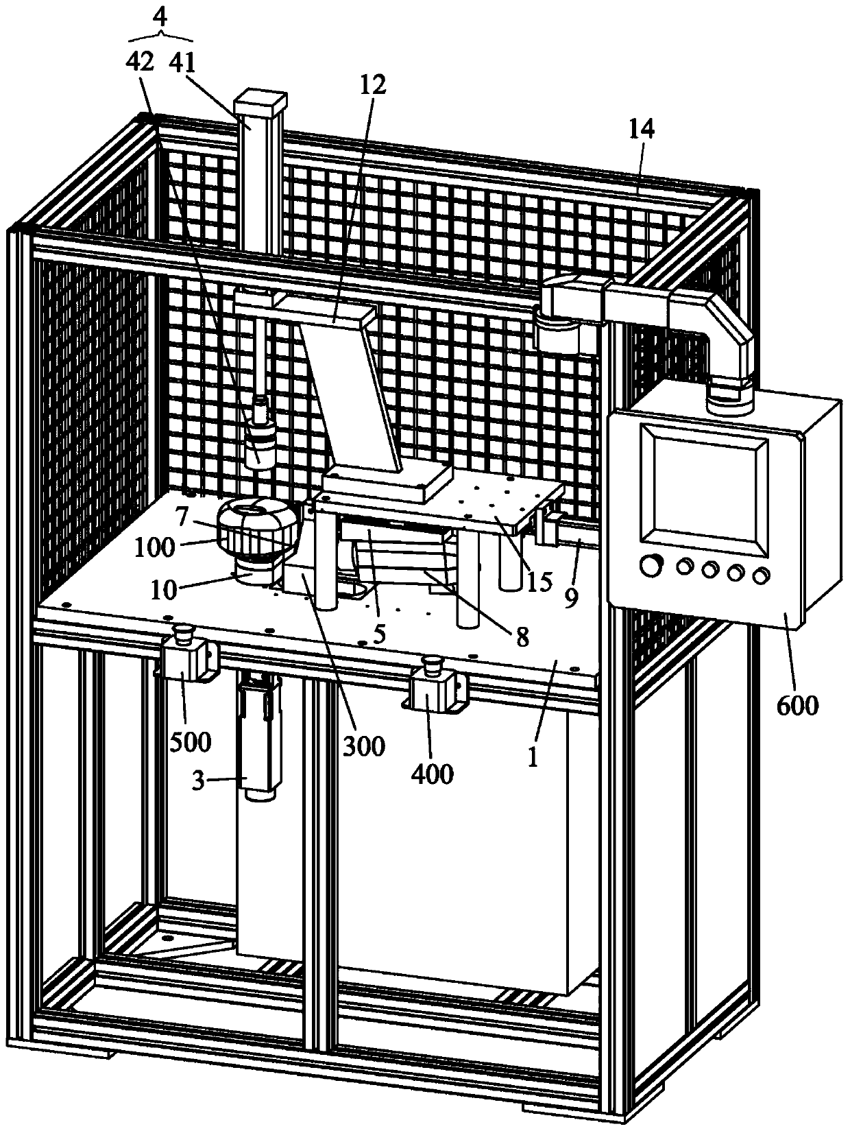
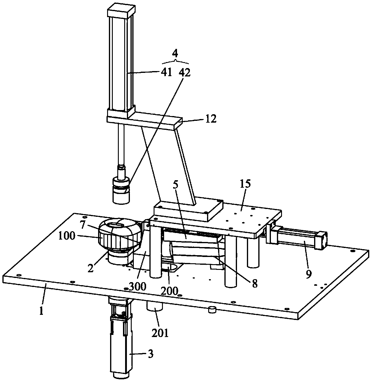
Chamfering machine

A chamfering machine and chamfering technology, applied in the field of chamfering machines, can solve problems such as poor processing quality, high equipment cost, and high cost of consumables, and achieve the effects of improving chamfering quality, low processing cost, and strong versatility

Pending Publication Date: 2019-09-17
周小玲
View PDF0 Cites 6 Cited by
  • Summary
  • Abstract
  • Description
  • Claims
  • Application Information

AI Technical Summary

Problems solved by technology

[0003] There are three traditional methods of chamfering and burring: 1. Grinding with an angle grinder or a straight grinder, but the grinding wheel has sand, dust and iron filings, resulting in low efficiency, dangerous operation and poor processing quality ( For example, the problem of uneven chamfering size); 2. Carrying out by turning or milling, this processing method has extremely low efficiency, and is mainly suitable for chamfering and deburring of cylindrical workpieces, but cannot be used for ellipse, square or Processing of heterogeneous workpieces; 3. Vibrating screen or polishing machine, this processing method has the problems of high equipment cost, high cost of consumables and unstable processing quality (such as uneven chamfer size)

Method used


Image

  • Chamfering machine
  • Chamfering machine
  • Chamfering machine

Examples


Embodiment Construction

[0024] The technical solutions in the embodiments of the present invention will be clearly and completely described below with reference to the accompanying drawings. Obviously, the described embodiments are only a part of the embodiments of the present invention, rather than all the embodiments. Based on the embodiments of the present invention, all other embodiments obtained by those of ordinary skill in the art without creative efforts shall fall within the protection scope of the present invention.

[0025] It should be noted that if there are directional indications (such as up, down, left, right, front, back, top, bottom, inside, outside, vertical, horizontal, vertical, counterclockwise, clockwise, circumferential direction, radial direction, axial direction, etc.), the directional indication is only used to explain the relative positional relationship, movement situation, etc. When a change occurs, the directional indication also changes accordingly.

[0026] In additi...


PUM


Abstract

The invention discloses a chamfering machine. A limiting part is arranged on a movable base or a chamfering tool; the movable base is driven by a feeding device to drive a cutting portion and the limiting part of the chamfering tool to respectively and tightly abut against a chamfering area of the end face of a workpiece and an area, close to the end face, of the side surface of the workpiece; a supporting table drives the workpiece to rotate under driving by a first drive device during processing; a tool rod drives the chamfering tool to rotate under driving by a second drive device and performs chamfering on the to-be-chamfered area of the end face, abutting against the chamfering tool, of the workpiece; in the chamfering process, due to the fact that the limiting part and the area, close to the end face, of the side surface of the workpiece are against and slide relatively, the chamfering size of the to-be-chamfered area of the end face of the workpiece can be controlled by the chamfering tool, so that the uniform chamfering of the to-be-chamfered area of the end face of the workpiece is realized, the chamfering quality is improved, and the chamfering machine is applicable to chamfer and chip removal processing of workpieces in round, elliptical, square or special shapes an the like, universality and efficiency is high, and the processing cost is low.

Description

technical field [0001] The invention relates to the technical field of machining, in particular to a chamfering machine. Background technique [0002] For many workpieces (especially the shell-shaped metal workpieces that are stamped or stretched, and the shell-shaped plastic workpieces that are blow-reversed), the outer edge of the end face is often sharp or has burrs after being formed, which requires chamfering or deburring. [0003] There are mainly three traditional ways of chamfering and burring: 1. Grinding by angle grinder or straight grinder, but the grinding wheel has sand, dust and iron filings, which has low efficiency, dangerous operation and poor processing quality ( For example, the problem of uneven chamfer size); 2. Through turning or milling, this processing method has extremely low efficiency, and is mainly suitable for chamfering and deburring of cylindrical workpieces, but cannot be used for oval, square or 3. It is processed by vibrating screen or poli...

Claims


Application Information

Patent Timeline
Patent Type & Authority Applications(China)
IPC IPC(8): B23D79/00B23Q3/06B23Q5/04B23Q5/34
CPCB23D79/00B23Q3/062B23Q5/04B23Q5/34
Inventor 周小玲
Owner 周小玲
Why Eureka
Try Eureka